
Octavia Mk1
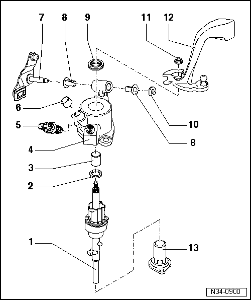
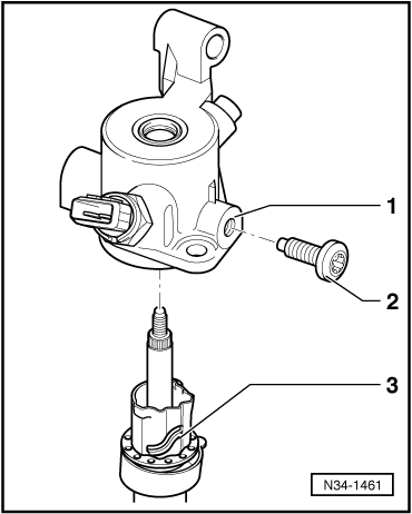
| 1 - | Gearshift shaft |
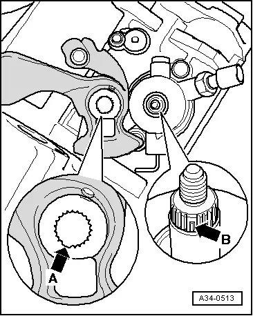
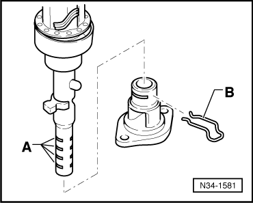
| q | As of gearbox manufacturing date 04 09 0, the latching sleeve is modified so that the gearshift shaft can be guided into the 4th gear shift gate when shifting down from the 5th gear to the 4th gear → Fig. |
| q | as of gearbox manufacturing date 06 08 01, additional catch in the screw cap → Fig. |
| q | assign according to → Electronic Catalogue of Original Parts |
| 2 - | Stop ring |
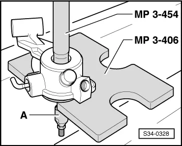
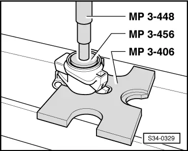
| 3 - | Ball sleeve |
| q | removing → Fig. |
| q | installing → Fig. |
| q | always replace → Electronic Catalogue of Original Parts |
| 4 - | Shift cover |
| q | as of gearbox manufacturing date 04 09 0 with an additional screw, so that the gearshift shaft can be guided into the 4th gear shift gate when shifting down from the 5th gear to the 4th gear → Fig. |
| q | assign according to → Electronic Catalogue of Original Parts |
| 5 - | Reversing light switch -F4-, 20 Nm |
| q | Grease peg lightly with grease for plug serration of clutch disc -G 000 100- |
| 6 - | Cap |
| q | for gearbox bleeder |
| 7 - | Reversing lever |
| q | Fitting position → Chapter |
| 8 - | Bushing |
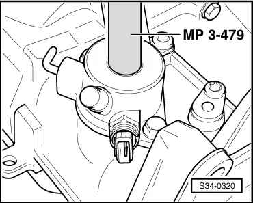
| 9 - | Gasket ring |
| q | release with a screwdriver |
| q | Fill half the space between the sealing lips and dust lips with sealing grease -G 052 128 A1- |
| q | installing → Fig. |
| 10 - | Lock washer |
| q | always replace → Electronic Catalogue of Original Parts |
| 11 - | 20 Nm |
| q | self-locking |
| q | always replace → Electronic Catalogue of Original Parts |
| 12 - | Gearbox shift lever |
| q | insert in such a way that the interrupted spacing of the teeth matches the gearshift shaft → Fig. |
| q | may be replaced with the gearshift mechanism mounted |
| q | Fitting position → Chapter |
| 13 - | Screw cap |
| q | as of gearbox manufacturing date 06 08 01 with catch for the gearshift shaft → Fig. |
|
|
|
|
|
|
|
|
|
|
|
|