skoda Workshop Repair Guides

Skoda Workshop Service and Repair Manuals

Differential gear for rear final drive > < Disassembling the rear final drive
Assembling the rear final drive
   
–  First press the plate housing out of the cover for Haldex coupling.
  N39-1016
–  Insert head bevel gear with drive shaft.
–  Position left cover with new O-ring.
–  Moisten O-ring with gear oil.
–  Tighten screws to tightening torque → Item.
  N39-0102
–  Insert right cover with differential gear and new O-ring -A- (moisten with gear oil), screw in the screws uniformly crosswise.
–  Tighten screws to tightening torque → Item.
–  Press the ventilation into the rear axle housing.
  N39-0758
Push out the old circlip from the flange shaft groove with the new circlip -A-.
–  Drive in the flange shaft on the right and left with a plastic hammer.
–  Fit on adjusting washer S3.
  V34-2005
–  Insert new O-ring -A- into the round slot of the secondary shaft housing and moisten with gear oil.
–  Position secondary shaft housing with shank bevel gear.
Fitting position:
The oil filter mount is located above the oil filler plug.
  N39-0756
–  Cover all the nuts -arrows- with locking agent -D 197 300 A1- and tighten crosswise in stages to tightening torque → Item.
  N39-0821
–  Insert the washer -1- for axial needle bearing with the shoulder pointing towards the axial needle bearing -2--arrow A- into the secondary shaft housing.
–  Then fit on the axial needle bearing -2-.
–  Subsequently insert the thrust washer -3- with the larger smooth surface -arrow B- pointing towards the hub -4-.
–  Now push the hub -4- onto the shank bevel gear with the 3 holes -arrow C- pointing upward.
  N39-1041
–  Afterwards, fit the first inner plate -2- into the secondary shaft housing -1-.
–  After this, insert the first outer plate -3- and subsequently position the remaining 6 inner plates and 6 outer plates.
  N39-1042
–  When installing the cam disc -A-, make sure that the cam path remains visible.
Fitting position:
The reverse teeth of the hub -arrows- must thereby grip into the interrupted spacing of the 3 teeth.
  N39-1046
–  When inserting -arrows-, turn the plate housing -A- and while doing so guide the housing to the cam disc/plate package up to the stop.
–  Place the 3 rollers -B- into the recesses of the plate housing.
–  Then place the 6 castors -C- into the plate housing as well.
  Note
The rollers and castors can only be inserted in one position because of the shape inside the plate housing.
–  Then install the ring -D-.
  N39-1043
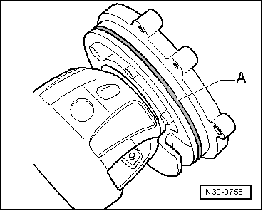
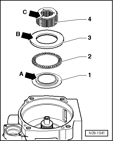
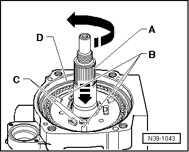
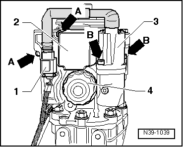
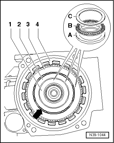
–  Position the thicker thrust washers -A- onto the castors and rollers in the plate housing.
–  After this, fit on the axial needle bearings -B- and the thinner thrust washers -C- for axial needle bearing.
  Note
t  
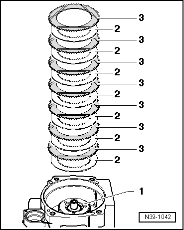
These individual axial needle bearing packages 1 through 3 are assigned to the diameters of the pistons for Haldex coupling.
t  
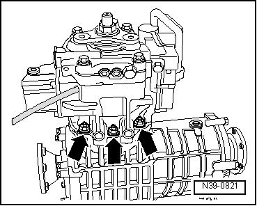
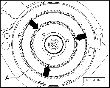
Make sure that the gap -arrow- between the axial needle bearing packages 2 and 3 is of equal size all around.
–  Insert the disc spring -4- with the large Ø (concave side) pointing towards the ring ( → Anchor, fig. N39-1043).
  N39-1044
–  Moisten O-rings -arrows A- and -arrow B- with high efficiency oil for Haldex coupling and insert them into the cover for Haldex coupling.
–  Pull out the middle piston -arrow C- approx. 5 mm uniformly across the entire circumference.
  S39-0435
–  Carefully position the cover for Haldex coupling -1- onto the secondary shaft housing -2-.
–  Screw in the fixing screws -arrows- crosswise in stages, each time 1/2 turn.
–  The gap -arrow A- must decrease uniformly.
  Note
The screws must not be tight when there is a gap. The axial needle bearing packages could have slipped towards the piston. Then remove the cover again and re-align the axial needle bearing.
–  Tighten screws to tightening torque → Item.
  N39-1047
–  Attach the cover -A- with new gasket to the secondary shaft housing -arrows-. Thus pay attention to the different versions of the covers, → Fig.
  N39-1040
–  Install oil filter -4- and tighten to tightening torque → Item.
–  Install pump for Haldex coupling -V181--3- and four-wheel drive control unit -J492--2-. Tighten screws -arrows A- and -arrows B- to tightening torque → Item.
–  Mount plug -1- for pump for Haldex coupling.
–  Before installing, lightly oil new gasket ring on the outside diameter and between the sealing lips with high efficiency oil -G 052 175 A1- for the Haldex coupling.
  N39-1039
–  Drive in new gasket ring until flush.
–  Install flange/propshaft.
  N39-0753
–  Insert new nut with locking agent -D 000 600- and tighten to tightening torque → Item.
A - Screws M 10 x 20
  Note
When tightening the nut, counterhold the flange/propshaft via the stop plate -T30012/1A (3221/1A)- with the bolted counterholder -T30004 (3415)-.
–  Remove rear final drive from assembly stand.
  S39-0133
–  Install bracket -arrow- for electrical cable at rear final drive.
  N39-1038

Differential gear for rear final drive > < Disassembling the rear final drive