skoda Workshop Repair Guides

Skoda Workshop Service and Repair Manuals

Setting drive shaft up to gearbox manufacturing date 18 05 3 > < Disassembling and assembling the drive shaft
Disassembling and assembling the drive shaft up to gearbox manufacturing date 18 05 3
Special tools and workshop equipment required
t  
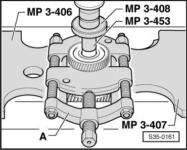
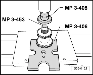
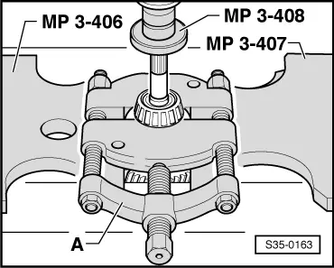
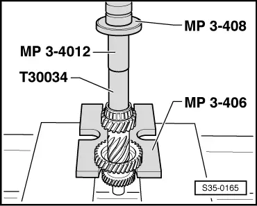
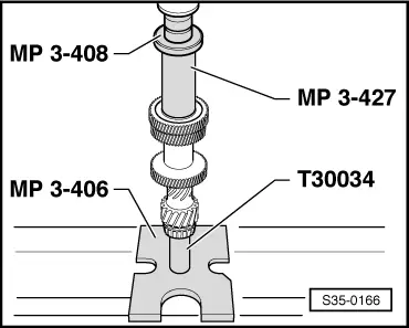
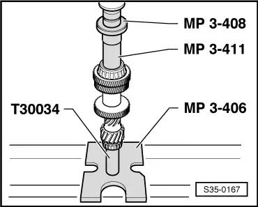
Pressure plate -MP3-406 (VW 401)-
t  Pressure plate -MP3-407 (VW 402)-
t  
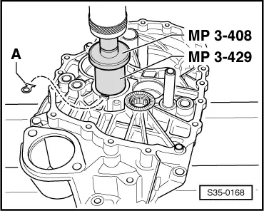
Pressure spindle -MP3-408 (VW 412)-
t  Thrust piece -MP3-411 (VW 454)-
t  
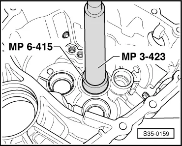
Pressure spindle -MP3-423 (VW 407)-
t  Drive bushing -MP3-427 (40 - 21)-
t  Pipe section -MP3-429 (2010)-
t  
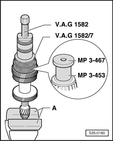
Thrust piece -MP3-453 (VW431)-
t  Thrust plate -MP3-467 (40-105)-
t  Pipe section -MP3-4012 (VW 416 B)-
t  Washer -MP6-415 (3260)-
t  
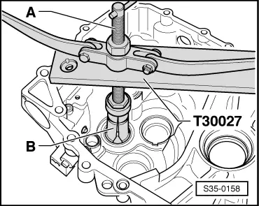
Retaining plate -T30027 (VW 801)-
t  Knock-in bushing -T30034 (41 - 501)-
t  Thrust piece -T30042 (2050)-
t  Tapered-roller bearing extractor -V.A.G 1582-
t  Gripper -V.A.G 1582/7-
t  Interior extractor 46...58 mm, e.g. -Kukko 21/7-
t  Separating device 22...115 mm, e.g. -Kukko 17/2-
t  Extractor, e.g. -Kukko 18/1-
t  Countersupport e.g. -Kukko 22/2-
   
  Note
t  When installing new pinions observe the technical data → Chapter.
t  If the position of the tapered-roller bearing is influenced when parts are replaced the drive shaft must be reset. Setting overview → Chapter.
t  Both tapered-roller bearings are replaced together.
1 - Gearbox housing
2 - Adjusting washer
q   Determine thickness → Chapter
3 - Outer ring/tapered-roller bearing
q   removing → Fig.
q   installing → Fig.
4 - Circlip
q   determine once again when replacing the tapered-roller bearing Pos. 5 and the drive shaft Pos. 8 → Fig.
5 - Inner ring/tapered-roller bearing
q   remove → Fig.
q   pressing on → Fig.
6 - 5th gear pinion
q   pressing off → Fig.
q   pressing on → Fig.
7 - 3rd/4th and 6th gear pinion
q   pressing off → Fig.
q   pressing on → Fig.
8 - Drive shaft
q   adjust → Chapter
9 - Inner ring/tapered-roller bearing
q   pressing off → Fig.
q   pressing on → Fig.
10 - Outer ring/tapered-roller bearing
q   removing → Fig.
q   Fitting position → Fig.
q   installing → Fig.
11 - Clutch housing

   
Remove outer ring/tapered-roller bearing from gearbox housing
A - Countersupport, e.g. -Kukko 22/2-
B - Interior extractor 46...58 mm, e.g. -Kukko 21/7-
  S35-0158
Press in outer ring/tapered-roller bearing in the gearbox housing
–  First position adjusting washer under outer ring.
–  Support the gearbox housing with a thrust piece -T30042 (2050)- directly below the bearing support.
  S35-0159
Removing inner ring/tapered-roller bearing
A - Protective jaws/vice
–  First remove the circlip.
–  Before fitting the extractor position the thrust piece -MP3-453 (VW431)- and the thrust washer -MP3-467 (40-105)- on the drive shaft.
  S35-0160
Pressing out 5th gear pinion
A - Separating device 22...115 mm, e.g. -Kukko 17/2-
  S35-0161
Pressing out 3rd/4th and 6th gear pinion
  S35-0162
Pressing off inner ring/tapered-roller bearing
A - Separating device 22...115 mm, e.g. -Kukko 17/2-
  S35-0163
Pressing on 3rd/4th and 6th gear pinion
–  Heat pinion to approx. 100 °C.
–  Press on the gear pinion forcefully so that the heat is not transfered immediately onto the drive shaft.
  S35-0164
Press on inner ring/tapered-roller bearing
  S35-0165
Pressing on 5th gear pinion
  Note
The nut on the 5th gear pinion must point upwards to the press-on tool.
  S35-0166
Press on inner ring/tapered-roller bearing
–  Determine the circlip → Fig. and install.
  S35-0167
Determining the circlip
–  Determine the thickest circlip - that can be fitted - and insert.
The following circlips are available:
  N35-0235
Thickness (mm)
1,791,92
1,831,95
1,861,98
1,89 

Part number → Electronic Catalogue of Original Parts.
   
Remove outer ring/tapered-roller bearing from clutch housing
A - Countersupport, e.g. -Kukko 22/2-
B - Interior extractor 46...58 mm, e.g. -Kukko 21/7-
  N35-0223
Fitting position of outer ring/tapered-roller bearing in clutch housing
Recesses for the lock washer (⇒ figure S35-0168) at outer ring/tapered-roller bearing -arrow A- and clutch housing -arrow B- must be positioned above one another.
  N35-0314
Pressing on outer ring/tapered-roller bearing
–  After the pressing in procedure, check if the lock washer -A- can be inserted into the recess.
  Note
The lock washer -A- must only be installed and screwed down after inserting the drive shaft.
  S35-0168

Setting drive shaft up to gearbox manufacturing date 18 05 3 > < Disassembling and assembling the drive shaft