skoda Workshop Repair Guides

Skoda Workshop Service and Repair Manuals

Summary of components - Vehicles with right-hand drive > < Connecting brake lines from the master brake cylinder to the hydraulic unit - Vehicles with left-hand drive
Removing and installing control unit and hydraulic unit - Vehicles with left-hand drive
Special tools and workshop equipment required
t  Brake pedal load e.g. -V.A.G 1869/2-
Removing:
Fitting location:
The control unit is bolted to the hydraulic unit and is located on the right of the engine compartment.
  WARNING
The brake lines around the hydraulic unit must not be bent!
–  Read out and note the actual control unit coding → Vehicle diagnostic tester.
–  Remove battery → Electrical System; Rep. gr.27.
–  Remove engine cover.
1.9 ltr. diesel engine:
–  Remove connecting hose to induction pipe → Engine; Rep. gr.21
–  Remove intake manifold flap motor -V157- → Engine; Rep. gr.23 (except vehicles with engine identification characters BJB).
2.0 ltr. diesel engine:
–  Remove intermediate wall for the plenum chamber → Body Work; Rep. gr.66.
–  Remove connection pipe between intake hose and exhaust turbocharger.
–  Remove top toothed belt guard.
Diesel engines with the diesel particle filter:
–  Remove the front exhaust pipe with diesel particle filter → Diesel engine; Rep. gr.26.
Continued for all vehicles:
   
–  Release the plug at the control unit, to do so pull the lever -1- downwards in -direction of arrow 1-. The lever -2- is released.
–  Pull the lever -2- upwards in -direction of arrow 2-.
–  Unplug the connector -3- in -direction of arrow 3- from the control unit.
–  Position brake pedal load e.g. -V.A.G 1869/2-.
–  Attach the bleeder hose of the bleeding bottle onto the bleeder screws of the front left and rear left brake caliper and open the bleeder screws.
–  Press down brake pedal with brake pedal load e.g. -V.A.G 1869/2- at least 60 mm.
–  Close front left and rear left bleeder screws.
  Note
Do not remove brake pedal load, e.g. -V.A.G 1869/2-.
–  Place sufficient non-fluffing cloths under the control unit and the hydraulic unit.
–  Extract as much brake fluid as possible from the brake fluid reservoir.
  Note
Make sure that no brake fluid gets onto the contacts of the plug connections.
  S45-0163
–  Mark both brake lines from the master brake cylinder -A- and -B- and unscrew from the hydraulic unit.
–  Close the brake lines and threaded holes immediately with plugs from the repair kit -1H0 698 311 A-.
–  Mark the brake lines (for brake calipers) -1- to -4-, unscrew and close with plugs from the repair kit -1H0 698 311 A-.
  S45-0162
–  Pull hydraulic unit with control unit upwards and out of the rubber bearings in -direction of arrow-.
–  Unscrew the bracket from the hydraulic unit.
Unscrew control unit of the hydraulic unit
–  Place the hydraulic unit with the control unit upwards on a clean and level surface.
  S45-0164
–  Release screws -arrows-.
  S45-0165
–  Detach the control unit without tilting from the hydraulic unit -arrow-.
–  Carefully pull off all gasket rings from the valve domes of the hydraulic unit.
  WARNING
t  On a disconnected control unit, the printed circuit board is exposed.
t  No humidity and dirt particles must penetrate into the inside of the control unit.
t  The hydraulic pump must not be separated from the hydraulic unit.
–  Cover the solenoid coils of the control unit with a non-fluffing cloth.
After separating from the control unit and hydraulic unit use the transport protection for valve domes.
Mount new control unit onto the hydraulic unit
  WARNING
Strong vibrations (e.g. fall, knock) can destroy the control unit. The control unit must no longer be used.
l  The surfaces must be cleaned before assembling.
  S45-0166
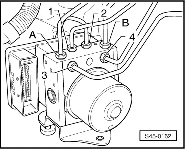
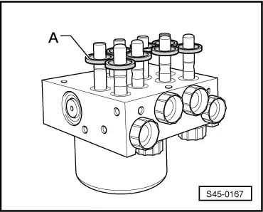
–  Push all the gasket rings -A- a little over the valve domes.
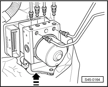
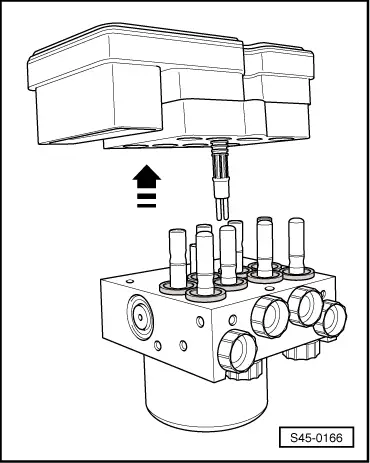
–  Position the control unit without tilting it onto the hydraulic unit.
Thus the gasket rings are brought into their end position.
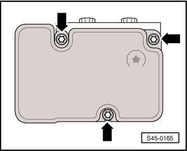
–  Screw hydraulic unit and control unit with the enclosed new Torx screws.
  Note
t  A new control unit may only be installed maximum twice onto the remaining hydraulic unit, in order to ensure tightness of the elastic seal.
t  A control unit, which was once operational, must not be mounted a second time.
Installing:
  Note
t  
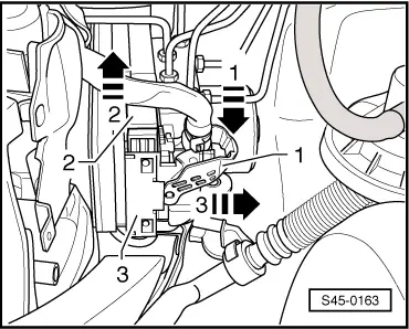
Only then remove plugs from the new hydraulic unit when the relevant brake line is installed.
t  If the plugs were already removed from the hydraulic unit before the brake line is installed, then brake fluid may escape and adequate filling and bleeding can no longer be guaranteed.
–  Screw the bracket onto the hydraulic unit and tighten to the recommended tightening torque.
–  Moisten the bolt of the support → Item with lubricant, e.g. -D 007 000 A2-, before inserting into the rubber bearings.
  S45-0167
–  Insert the hydraulic unit with the control unit into the rubber bearings of the console against the -direction of arrow-.
–  Remove the plugs consecutively from the brake lines and the ABS hydraulic unit.
–  Screw the marked brake lines onto the hydraulic unit.
  S45-0164
–  Connect the plug -3- to the control unit against the -direction of arrow 3-.
–  Push the lever -2- against the -direction of arrow 2-.
–  Lock the plug at the control unit, to do so pull the lever -1- upwards in -direction of arrow 1-. The lever -2- is locked.
Diesel engines with the diesel particle filter:
–  Install front exhaust pipe with diesel particle filter → Diesel engine; Rep. gr.26.
Continued for all vehicles:
1.9 ltr. diesel engine:
–  Install intake manifold flap motor -V157- → Engine; Rep. gr.23 (except vehicles with engine identification characters BJB).
–  Install connecting hose to induction pipe → Engine; Rep. gr.21.
2.0 ltr. diesel engine:
–  Install top toothed belt guard.
–  Install connection pipe between intake hose and exhaust turbocharger.
–  Install the intermediate wall for the plenum chamber → Body Work; Rep. gr.66.
–  Install battery → Electrical System; Rep. gr.27.
  Note
If the battery earth strap is disconnected and connected, carry out certain additional operations → Electrical System; Rep. gr.27.
–  Position engine cover.
–  Remove brake pedal load e.g. -V.A.G 1869/2-.
–  Bleeding brake system → Chapter.
–  Code the control unit -J104- → Vehicle diagnostic tester.
  S45-0163
Tightening torques:
Control unit to hydraulic unit5.5 Nm
Screw for hydraulic unit to bracket 8 Nm
Brake lines to ABS unit: 
Thread M 10 x 114 Nm
Thread M 12 x 114 Nm


Summary of components - Vehicles with right-hand drive > < Connecting brake lines from the master brake cylinder to the hydraulic unit - Vehicles with left-hand drive