
Octavia Mk2
| Summary of components |
| Testing compression pressure → Chapter. |
 Note
Note| t | When installing a replacement cylinder head, all the contact surfaces between the hydraulic tappets, the cam followers and the cam tracks must be oiled before installing the cylinder head cover. |
| t | Do not remove the plastic bases supplied as a protection for the open valves until just before fitting on the cylinder head. |
| t | If the cylinder head is replaced, also the entire coolant must be replaced. |
| t | Before assembly moisten all bearing and contact surfaces with oil. |
| t | Disassembling and assembling intake manifold → Chapter. |

| 1 - | Cable guide |
| q | Tighten at camshaft housing to 8 Nm |
| 2 - | 10 Nm |
| 3 - | 10 Nm + torque a further 90° (1/4 turn) |
| q | replace |
| q | unscrew from the outside to the inside → Chapter |
| q | tighten from the inside to the outside → Chapter |
| 4 - | 8 Nm |
| 5 - | to air filter |
| 6 - | Hall sender -G40- |
| 7 - | O-ring |
| q | replace if damaged |
| 8 - | Coolant pipe with bracket |
| 9 - | Mounting pin, 6 Nm |
| q | Engine cover with air filter |
| 10 - | Cylinder head bolt |
| q | replace |
| q | observe the mounting instructions and sequence for loosening and tightening → Chapter |
| 11 - | Roller rocker arm |
| q | inspect roller bearings for smooth operation |
| q | oil contact surface |
| q | to install clip onto the supporting element with the locking clips |
| 12 - | Supporting element |
| q | do not interchange |
| q | with hydraulic valve clearance compensation |
| q | oil contact surface |
| 13 - | Dowel pins |
| 14 - | Oil pressure switch 0.05 MPa (0.5 bar) -F1-, 25 Nm |
| q | check → Chapter |
| q | Cut open gasket ring if leaking and replace |
| 15 - | Cylinder head |
| q | removing and installing → Chapter |
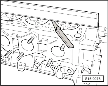
| q | check for distortion → Fig. |
| q | Sealing surfaces to the camshaft housing must be free of oil and grease. |
| q | after replacing fill entire system with fresh coolant |
| 16 - | Cylinder head gasket |
| q | replace |
| q | metal gasket |
| 17 - | Guide bolt |
| q | Tightening torque: 20 Nm |
| 18 - | Screw cap |
| q | replace if leaking |
| Removing: |
| – | Pierce through the centre using an expanding mandrel and pull out as straight as possible using a suitable tool. |
| Make sure the sealing surface on the cylinder head is not damaged. |
| Installing: |
| – | Thoroughly clean the sealing surface in the cylinder head |
| – | Thinly coat the new screw cap sideways all around with sealant -D 154 102 A1-. |
| – | Drive screw cap with drift pin e.g. pressure plate -MP 3-410 (VW 434)- straight into the hole. |
| l | The finishing edge of the screw cap must be approx. 1 mm deep in relation to the end face of the cylinder head. |
| – | Wipe off any sealant oozing out. |
| 19 - | Lifting eye |
| 20 - | 20 Nm |
| 21 - | Oil filter |
| q | inserted into the cylinder head |
| q | replace |
| 22 - | Gasket ring |
| q | replace |
| q | 4 pieces |
| q | inserted into the cylinder head (groove) |
| q | not fitted on all the engines, observe the different seals of the camshaft housing → Chapter |
| 23 - | Camshaft housing |
| q | removing and installing → Chapter |
| 24 - | Bucket tappets |
| q | oil contact surface |
| 25 - | O-ring |
| q | replace |
| 26 - | High pressure-fuel pump |
| q | for fuel supply |
| q | with fuel pressure regulating valve -N276 - |
| q | Can only be replaced complete with fuel pressure regulating valve -N276- and screw neck for fuel lines. |
| q | Do not unscrew cap! |
| q | Do not unscrew screw neck for fuel lines and fuel pressure regulating valve -N276-! |
| q | removing and installing → Chapter |
|
|