skoda Workshop Repair Guides

Skoda Workshop Service and Repair Manuals

Bracket for auxiliary units with oil filter and engine oil cooler > < Removing and installing oil pump
Removing and installing the upper part of the oil pan
Special tools and workshop equipment required
t  Assembly tool -T10118-
t  Cleaning and degreasing agent, e.g. -D 000 401 04-
t  Sealant remover gasket stripper (bearing code GST, part number R 34402), manufacturer Retech s.r.o.
t  Silicone sealant -D 174 003 A2-
Removing
–  Remove the sealing flange on the gearbox side → Chapter.
–  Remove oil pump → Chapter.
–  Remove the front right wheelhouse liner → Body Work; Rep. Gr.66.
Vehicles with auxiliary heating.
   
–  Slacken the clamp -1- and release the screw -2-.
–  Remove silencer for auxiliary heating.
Continued for all vehicles
  A10-10778
–  Screw out screws -arrows-.
–  Remove charge-air pipe. To do so lift retaining clips -pos. 1 and 2-.
–  Unscrew charge-air pipe from upper part of oil pan.
–  Unscrew bracket for wiring loom at upper part of oil pan.
For engines with identification characters CDAA, CDAB, CCZA
  A21-10162
–  Disconnect plug -1- from the valve for oil pressure control -N428 --3-.
Continued for all vehicles
  A17-10421
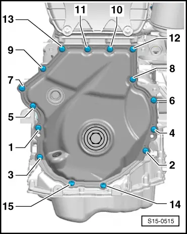
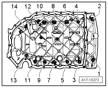
–  Release screws -14 and 15- from bottom cover for timing chain.
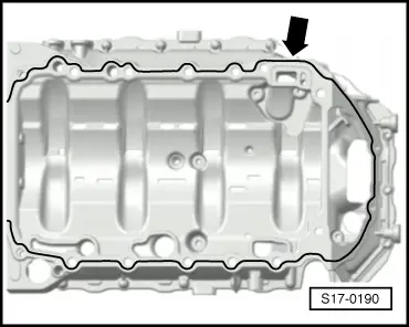
  Caution
In order to avoid future leakage, do not deform the bottom cover for the timing chain and do not grip between the screw points when pressing off the oil pan upper part.
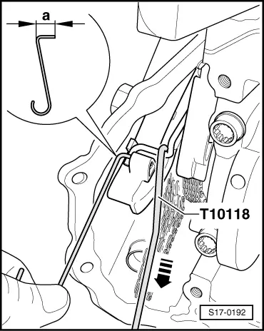
  WARNING
Risk of accident! When removing the upper part of the oil pan, the spring of the chain tensioner for the oil pump drive jumps from the upper part of the oil pan to the bottom cover for the timing chain. When removing the upper part of the oil pan, do not grip between the upper part of the oil pan and the bottom cover for the timing chain.
  S15-0515
–  Release screws -1 through 14- and remove upper part of oil pan. It may be necessary to loosen the upper part of the oil pan using light blows with a rubber hammer.
Install
  WARNING
Wear protective gloves when working with sealant and grease remover!
–  Remove residual sealant from the sealing surface on the cylinder block, the upper part of the oil pan and on the bottom cover for timing chain with chemical sealant remover.
–  Degrease the sealing surfaces.
–  Check the oil ducts in upper part of oil pan and in cylinder block for contamination.
  A17-10273
–  Make an auxiliary tool out of wire from Ø 1.8 to 2.0 mm, as shown in the illustration. Dimension -a- = approx. 10 mm.
–  Pull the tensioning spring of the drive chain tensioner for the oil pump with assembly tool -T10118 - in -direction of arrow- and secure by sliding the auxiliary tool into the hole (Ø 2.2 mm) in the tensioner.
  Note
t  Pay attention to the use by date on sealant.
t  The upper part of the oil pan must be installed immediately and tightened after applying the sealant.
  S17-0192
–  Cut off nozzle tube at the front marking (Ø of nozzle approx. 3 mm).
  A17-0081
–  Apply silicone sealant (as shown) -arrow- to the clean sealing surface of the upper part of the sealing flange.
l  The sealant bead must be 2...3 mm thick.
  Note
The sealant bead must not be thicker otherwise excess sealant may get into the oil pan and block the strainer in the oil pump suction pipe.
  S17-0190
–  Attach the upper part of the oil pan immediately and align it to the gearbox side flat to the cylinder block and tighten the new screws in the sequence -1 to 14- as follows:
–  1. Tighten screws to 15 Nm.
–  2. Torque screws a further 90°.
  A17-10273
–  Tighten new screws -14 and 15- to 8 Nm and torque a further 45° (1/8 turn).
–  Release the auxiliary tool from the drive shaft tensioner of the oil pump using a screwdriver.
Further installation occurs in reverse order. Pay attention to the following:
–  Install the sealing flange on the gearbox side → Chapter.
–  Install oil pump → Chapter.
  S15-0515

Bracket for auxiliary units with oil filter and engine oil cooler > < Removing and installing oil pump