
Octavia Mk2

| 1 - | 120 Nm + torque a further 90° (1/4 turn) |
| q | replace |
| q | do not oil |
| q | to release and tighten use counterholder -T30004- or counterholder -MP 1-310 (3099)- |
| 2 - | 20 Nm |
| q | self-locking, replace |
| 3 - | small guide pulley |
| 4 - | 20 Nm + torque a further 45° (1/8 turn) |
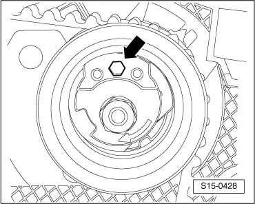
| 5 - | Tensioning pulley |
| q | The eccentric of the new version has an additional hole for 6 mm hexagon socket wrench → Fig. |
| 6 - | Toothed belt |
| q | mark the direction of rotation with chalk or a felt-tip pen before removing |
| q | check for wear |
| q | do not kink |
| q | removing → Chapter |
| q | install (set the timing) → Chapter |
| 7 - | 25 Nm |
| 8 - | Toothed belt sprocket of exhaust camshaft |
| q | Check fitting position |
| 9 - | 25 Nm |
| 10 - | Toothed belt sprocket of inlet camshaft |
| q | Check fitting position |
| 11 - | 100 Nm |
| q | to release and tighten use counterholder -T10051- |
| 12 - | 100 Nm |
| q | to release and tighten use counterholder -T10051- → Chapter |
| 13 - | Hub |
| q | for exhaust camshaft |
| q | to remove use extractor -T10052- |
| 14 - | Hub |
| q | for inlet camshaft with rotor for hall sender -G40- |
| q | to remove use extractor -T10052- → Chapter |
| 15 - | Rear toothed belt guard |
| 16 - | Rubber grommet |
| q | for the removal of the hall sender -G40- (rear toothed belt guard must not be removed) |
| q | replace if damaged |
| 17 - | 10 Nm |
| q | insert using locking agent -D 000 600 A2- |
| 18 - | O-ring |
| q | replace |
| 19 - | Coolant pump |
| q | removing and installing → Chapter |
| 20 - | 15 Nm |
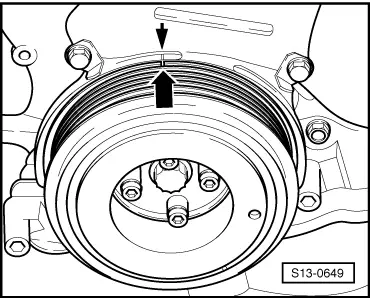
| 21 - | Toothed belt sprocket of crankshaft |
| q | there must not be any oil present on the contact surface between the toothed belt sprocket and the crankshaft |
| q | can be installed only in one position |
| 22 - | large guide pulley |
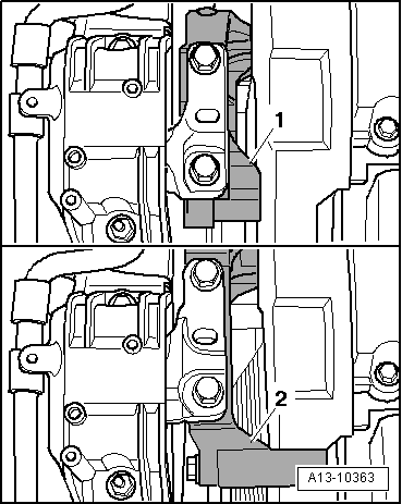
| 23 - | screw for guide pulley |
| q | replace |
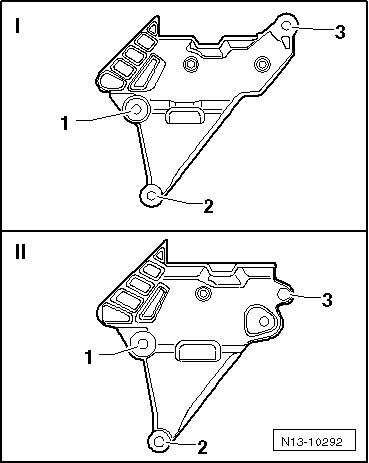
| q | different screws for vehicles with small or large engine support |
| q | Tightening torque: |
| t | Vehicles with small engine support: → Fig. |
| t | Vehicles with large engine support: → Fig. |
 Note
Note
|
|
|
|
Note
|
|
Note
|
|
 Caution