Octavia Mk2
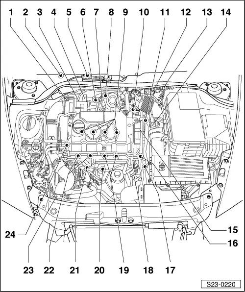
| Fitting locations for engine with engine identification characters BMM - Overview |
 Note
Note| t | Some components are fitted under the engine cover. |
| t | Remove engine cover → Chapter. |
| Components A through G are not represented in the overview figure. |
| A - | Warning light for engine electronics -K149- |
| q | in the dash panel insert |
| B - | Accelerator pedal position sender -G79- with accelerator pedal position sender 2 -G185- |
| q | in footwell on the accelerator pedal |
| C - | Brake light switch -F- and brake pedal switch -F63- |
| q | in footwell on the brake pedal |
| D - | Fuel pump relay -J17- |
| q | on relay carrier |
| E - | Clutch position sender -G476- |
| q | on clutch main cylinder |
| F - | Automatic glow period control unit -J179- |
| q | below E-box in the engine compartment |
| G - | Relay and fuse carrier |
| q | with relay for voltage supply tml. 30 -J317- |
| q | with relay for voltage supply tml. 15 -J329- |
| q | E-box in the engine compartment |
| 1 - | Intake manifold flap motor -V157- |
| 2 - | Exhaust gas temperature sender 3 -G495- (Temperature sender downstream particle filter -G527-) |
| 3 - | lambda probe -G39- with heating for lambda probe -Z19- |
| 4 - | electrical exhaust gas recirculation valve -N18- with EGR potentiometer -G212- and EGR control motor -V338- |
| 5 - | Diesel direct injection system control unit -J248- |
| 6 - | Exhaust gas temperature sender 2 -G448- (Temperature sender upstream particle filter -G506-) |
| 7 - | Pressure sensor 1 for exhaust gas -G450- |
| 8 - | Exhaust gas temperature sender 1 -G235- (Temperature sender upstream turbocharger -G507-) |
| 9 - | The unit injectors |
| q | Unit injector valve of cylinder 1 -N240- |
| q | Unit injector valve of cylinder 2 -N241- |
| q | Unit injector valve of cylinder 3 -N242- |
| q | Unit injector valve of cylinder 4 -N243- |
| q | Removing and installing unit injectors → Chapter |
| 10 - | Changeover valve for radiator of exhaust gas recirculation -N345- |
| 11 - | Coolant temperature sender -G62- |
| 12 - | Solenoid valve for charge pressure control -N75- |
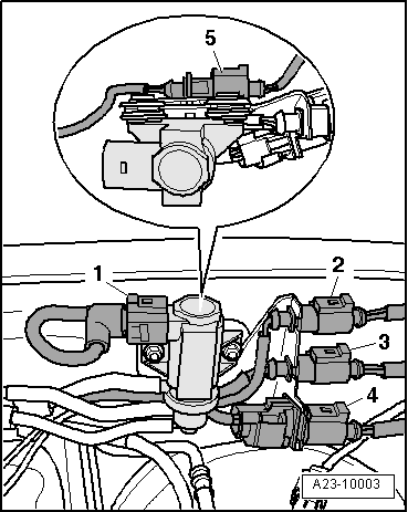
| 13 - | Plug connection |
| q | left on partition panel |
| q | Summary of components → Fig. |
| 14 - | Air mass meter -G70- |
| 15 - | Tandem pump |
| 16 - | Multipin plug connection |
| q | central for pump-nozzle units |
| 17 - | Engine speed sender -G28- |
| q | removing and installing → Chapter |
| 18 - | Fuel temperature sender -G81- |
| 19 - | Glow plugs |
| q | Glow plug 3 -Q12- |
| q | Glow plug 4 -Q13- |
| q | Removing and installing glow plugs → Chapter |
| 20 - | 3-pin plug connection |
| for hall sender -G40- |
| 21 - | Coolant temperature sender at radiator outlet -G83- |
| 22 - | Glow plugs |
| q | Glow plug 1 -Q10- |
| q | Glow plug 2 -Q11- |
| q | Removing and installing glow plugs → Chapter |
| 23 - | Charge pressure sender -G31- with intake air temperature sender -G42- |
| 24 - | Hall sender -G40- |
| q | for camshaft position |