skoda Workshop Repair Guides

Skoda Workshop Service and Repair Manuals

Removing and installing the sender for fuel gauge display G > < Removing and installing the fuel delivery unit on vehicles with front-wheel drive
Removing and installing the fuel delivery unit on vehicles with four-wheel drive
Special tools and workshop equipment required
t  
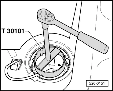
Wrench for the lock ring -T30101 (3087)-
t  Protective gloves
Condition
l  The fuel tank must not be more than 1/3 full.
Removing
  Note
t  If necessary, drain the fuel tank → Chapter.
t  Safety precautions when working on the fuel supply system → Chapter.
t  Observe the regulations concerning cleanliness when working on the fuel supply/injection system → Chapter.
–  Switch off the ignition and pull out the ignition key.
–  Removing rear seat bench → Body Work → Rep. Gr.72.
–  Remove the cover from the fuel delivery unit.
  Note
t  For vehicles with auxiliary heating, the plug connection for the dosing pump -V54- must also be disconnected.
t  
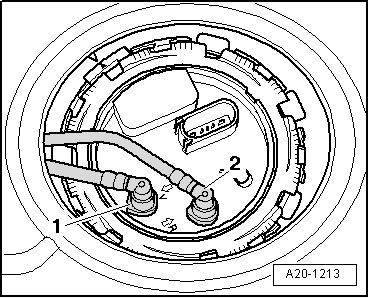
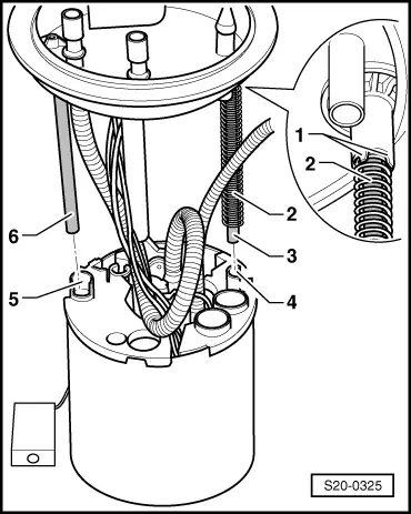
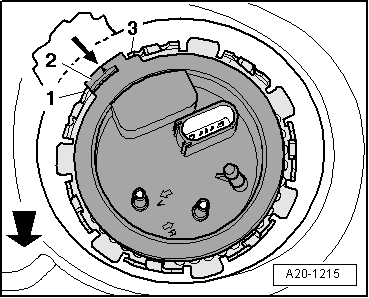
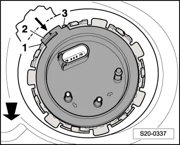
Two types of fuel delivery units are installed in the vehicles, which can be recognized on the different flanges.
Fuel delivery unit type 1
   
–  Disconnect the plug as well as the black fuel feed line -1- and the blue fuel return-flow line -2- from the flange.
  Note
t  Press in securing ring in order to unlock the lines.
t  For vehicles with auxiliary heating the suction hose for the dosing pump -V54- must be pulled out additionally (open lower clamp).
  A20-1213
–  Open lock ring with the wrench -T30101-.
–  Pull out closing flange and gasket ring of the fuel delivery unit from the opening of the fuel tank and place to the side with the connected lines.
  S20-0151
–  Separate through the opening of the fuel tank the jetstream line -1- to the suction jet pump, to do so press the release button.
–  Unhook the fuel delivery line -2- at the fuel delivery unit, to do so pull the catch to the top -arrow-.
  Note
t  You must wear protective gloves for removing the fuel delivery unit.
t  Take the fuel delivery unit out of the fuel tank in such a way that the electrical cables and the fuel hoses are not damaged and that the float arm of the sender for the fuel gauge display -G- is not bent.
t  You must empty the old fuel delivery unit before disposing of it if you wish to replace it.
–  Pull the fuel delivery unit out of the opening of the fuel tank.
Fuel delivery unit type 2
  A20-10042
–  Disconnect the plug as well as the black fuel feed line -1- and the blue fuel return-flow line -2- from the flange.
  Note
t  Press in securing ring in order to unlock the lines.
t  For vehicles with auxiliary heating the suction hose for the dosing pump -V54- must be pulled out additionally (open lower clamp).
  S20-0324
–  Open lock ring with the wrench -T30101-.
  S20-0151
–  Slightly raise the closing flange and check if the spring -2- is still fastened on the flange -1-.
   If the spring -2- lies loose on the guide pipe -3-, hold the spring with the fingers when removing the closing flange.
–  Pull out closing flange and gasket ring of the fuel delivery unit from the opening of the fuel tank and place to the side with the connected lines.
  S20-0325
–  Separate through the opening of the fuel tank the jetstream line -1- to the suction jet pump, to do so press the release button.
–  Pull off the fuel delivery line -2- from the fuel delivery unit.
  Note
t  You must wear protective gloves for removing the fuel delivery unit.
t  Take the fuel delivery unit out of the fuel tank in such a way that the electrical cables and the fuel hoses are not damaged and that the float arm of the sender for the fuel gauge display -G- is not bent.
t  You must empty the old fuel delivery unit before disposing of it if you wish to replace it.
–  Pull the fuel delivery unit out of the opening of the fuel tank.
Install
Installation occurs in reverse order to removal. Pay attention to the following:
–  Insert the fuel delivery unit into the fuel tank with the closing flange placed to the side. Thus, do not bend the float arm of the fuel gauge sender unit -G-.
–  Attach fuel delivery line and jetstream line.
–  Insert the new dry gasket ring into the opening of the fuel tank and moisten only from the inside with fuel for installing the closing flange.
Fuel delivery unit type 1
  A20-10381
–  Insert the spring -2- into the guide bore -arrow- and place the guide -1- of the closing flange onto the guide -3- at the fuel delivery unit.
Fuel delivery unit type 2
  A20-10043
l  The spring -2- must be fastened to the retaining lugs -1- of the closing flange.
–  First of all guide the guide pipe -3- into the guide bore -4-.
–  Then lower the closing flange in such a way that the guide pipe -6- locks into the guide bore -5-.
  Note
  S20-0325
Pay attention that the electrical lines -1- and the fuel feed line -3- are positioned as shown in the illustration so that they do not block the float arm -2-.
Continued for the fuel delivery unit type 1 and type 2
–  Press the closing flange to the bottom and move the closing flange into the fitting position.
Further information:
  A20-10383
Fuel delivery unit - type 1
  A20-1215
Fuel delivery unit - type 2
t  Observe the fitting location of the fuel delivery unit. The tabs -2- on the closing flange must be between the tongues -1- and -3- at the fuel tank. The -thick arrow- points in the direction of travel.
t  Tighten lock ring to 110 Nm.
t  Do not mix-up the fuel feed line and the fuel return-flow line.
t  Make sure the fuel lines fit tightly.
t  After installing the fuel delivery unit, check whether the fuel feed line and the fuel return-flow line are still clipped in place on the fuel tank.
  S20-0337

Removing and installing the sender for fuel gauge display G > < Removing and installing the fuel delivery unit on vehicles with front-wheel drive