skoda Workshop Repair Guides

Skoda Workshop Service and Repair Manuals

Transporting the gearbox > < Removing and installing the gearbox
Remove gearbox (Octavia II)
Special tools and workshop equipment required
t  Supporting device -T30099-
t  Shim -T30099/1-
t  Hook for MP9-200 and T30099 -MP9-200/10 (10-222A/10)-
t  Adjusting plate -3282/31-
t  Engine/gearbox jack (e.g. -V.A.G 1383 A-)
t  Gearbox attachment device -MP3-478 (3336)-
t  Gearbox mount -3282-
t  Grease for plug serration of clutch disc -G 000 100-
–  Remove engine cover → Engine; Rep. gr.10 (if present).
  Note
t  All cable straps which are detached or cut open when removing, should be fitted on again in the same place when installing.
t  After the battery earth strap is disconnected and connected, carry out additional operations → Electrical System; Rep. gr.27.
–  Disconnect the battery-earth strap with the ignition off → Electrical System; Rep. gr.27.
–  Remove battery and battery tray → Electrical System; Rep. gr.27.
–  Remove air filter → Engine; Rep. gr.24.
–  Remove the cooling water tank cover → Body Work; Rep. gr.66.
l  In order to avoid damage to the selector cable, the cable lock must be separated from the selector cable before removal.
   
–  Pull forward the locking mechanism as far as the stop in -direction of arrow 1-, then lock by turning to the left in -direction of arrow 2-.
  S34-1116
–  Remove lock washer -1- for shift cable from gearbox shift lever -2-.
–  Pull off shift cable from the stud of the gearbox shift lever.
The relay lever -4- is secured with a clip -3- in the cover
–  Unclip -3- out of the hole of the relay lever and pull out relay lever -4- together with the cable lock out of the cover.
  S34-1167
The relay lever is secured with a catch -arrow 1- in the cover
–  Carefully press down the catch -arrow 1- of the relay lever up to the stop.
–  Afterwards, carefully pull out the relay lever together with the cable lock -arrow 2- out of the bearing point in the cover. To do so move relay lever back and forward (direction of operation).
Continued for all vehicles
–  Remove the gearshift lever from the gearshift shaft.
  N34-10889
–  Remove Bowden cable support -arrows-.
–  Tie up shift cable and selector cable.
  N34-1821
–  Pull out the tube and hose line -A- from bracket -B- on the gearbox.
–  Remove slave cylinder -arrows-, lay aside and secure with wire. Do not open line system.
  Note
Do not depress the clutch pedal.
Vehicles with start-stop system
  N34-1822
–  Unplug the connector from the transmission neutral sender -G701--arrow-.
Continued for all vehicles
–  Remove the earth strap from the engine/gearbox connecting screw.
–  Remove engine/gearbox connecting screws at the top.
–  Remove fixing screw for starter at the top.
  N34-11273
–  Fit supporting device -T 30099-.
–  Slightly pre-tension the engine/gearbox unit via the spindles, do not raise.
–  Loosen the front left wheel bolts.
–  Raise vehicle.
–  Unscrew left front wheel.
–  Remove the noise insulation below the engine/gearbox → Body Work; Rep. gr.50.
–  Remove the front left wheelhouse liner → Body Work; Rep. gr.66.
  S34-1082
–  Disconnect plug -1- of the reversing light switch -F4-.
–  If present, remove nut -2-.
–  Remove starter (screw -3-) → Electrical System; Rep. gr.27.
  N34-1823
–  Separate the exhaust system, -arrows 1- and unscrew the holder for the exhaust pipe from the assembly carrier -arrows 2- → Engine; Rep. gr.26.
  N34-11039
–  Disconnect plug -1- for oil level and oil temperature sender -G266-.
  N34-10504
–  Remove the screen cap for drive shaft (if present) from the engine -arrows-.
–  Remove drive shafts from flange shafts and tie up as far as possible; do not damage the surface protection.
  S39-0282
–  Unscrew the engine/gearbox connecting screw -A- above the right flange shaft.
  N34-1825
–  Remove pendulum support -arrows°A-, -B- and -C-.
  N34-1826
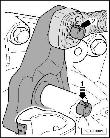
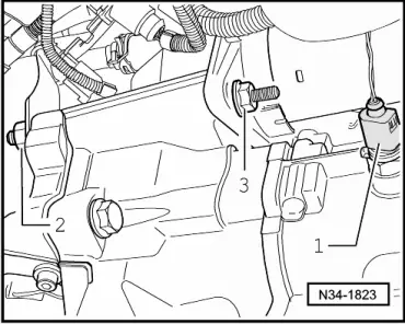
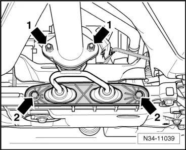
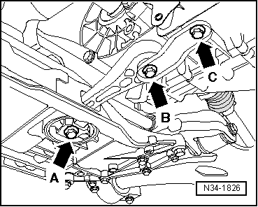
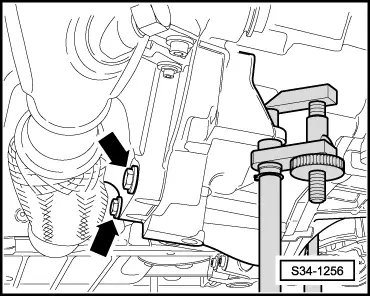
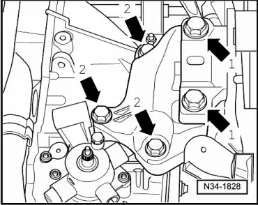
–  Remove the screws -arrows 1- of the left and right assembly carrier out of the gearbox mount.
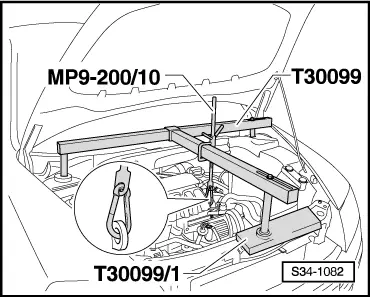
–  Move engine/gearbox unit into oblique position, to do so lower the supporting device -MP9-200 (10-222A)- via the spindle.
  Note
Observe all lines when lowering the gearbox.
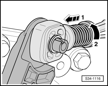
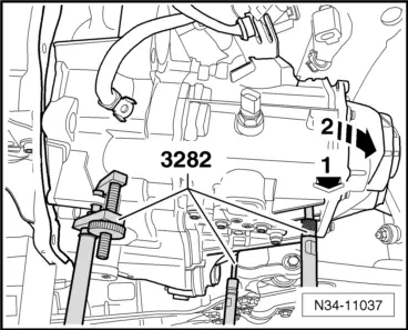
–  Remove gearbox console, to do so screw out the screws -arrows°2-.
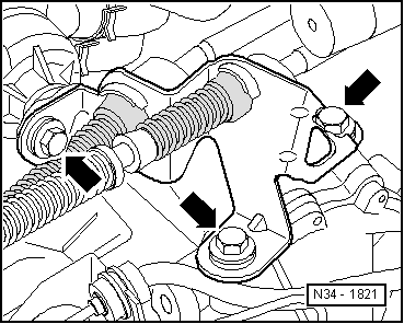
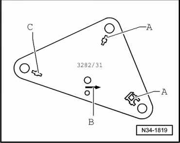
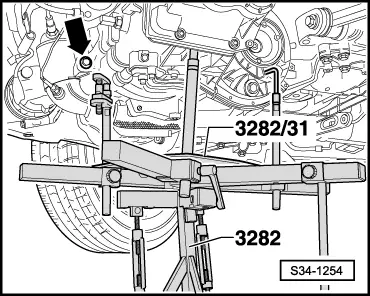
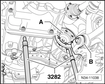
The gearbox mount -3282- is aligned for removal of the gearbox „0AJ“ by using the adjusting plate -3282/31-.
–  Insert gearbox mount -3282 - into engine/gearbox jack - V.A.G 1383 A-.
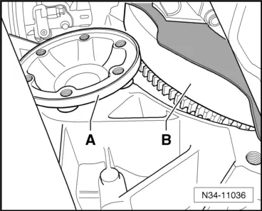
–  Position adjusting plate -3282/31 - onto the gearbox mount -3282- (adjusting plate fits in only one position).
–  Align arms of the gearbox mount to match the holes in the adjusting plate.
  N34-1828
–  Screw in mounting elements-A-, as shown on the adjusting plate.
–  Instead of the mounting element-C- screw in the lifting hook.
  Note
  N34-1819
The lifting hook is a component part of the gearbox mount -3282-.
–  Position engine/gearbox jack below vehicle, arrow -B- on adjusting plate points in the direction of travel/vehicle.
  S34-1168
–  Align the adjusting plate parallel to the gearbox.
  S34-1254
–  Insert the lifting hook in one of the recesses of the gearbox housing below the left flange shaft -arrow-.
–  Remove engine/gearbox connecting screw (-arrow- in the fig. S34-1254 → Anchor).
  S34-1255
–  Separate exhaust system so that the bottom screws -arrows- can be unscrewed (only on 1.4 engine).
–  Ask a second mechanic to carefully push the engine forwards.
–  Press the gearbox out of the sleeves.
  S34-1256
–  Press the gearbox in the area of the cover for the gearbox housing to the front end -arrow 1- and turn it slightly towards the bottom -arrow 2-.
–  Pay attention to the intermediate plate on the engine.
  N34-11037
–  After this, carefully guide the gearbox with the right flange shaft -A- past the flywheel -B- and the intermediate plate as shown.
  N34-11036
–  The left flange shaft -A- is carefully guided past the console -B- of the assembly carrier as shown.
–  Lower gearbox, to do so pay attention to the assembly carrier.
–  Change the gearbox position at the spindles of the gearbox mount -3282- when lowering.
  Note
Observe all lines when lowering the gearbox.
  N34-11038

Transporting the gearbox > < Removing and installing the gearbox