skoda Workshop Repair Guides

Skoda Workshop Service and Repair Manuals

Functional test > < Removing and installing shift cable and selector cable|Install
Setting the shift mechanism
Special tools and workshop equipment required
t  Rig pin -T10027A-
t  Release tool -T30098-
  Note
The following are required for correct setting of the shift mechanism:
l  Gearbox, clutch and clutch control in perfect condition
l  Shift mechanism operates freely
l  Operating and transmission elements of the shift mechanism are in perfect condition
l  Gearbox in Neutral
–  Remove air filter → Engine; Rep. gr.24.
   
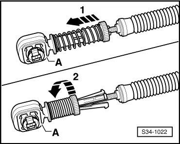
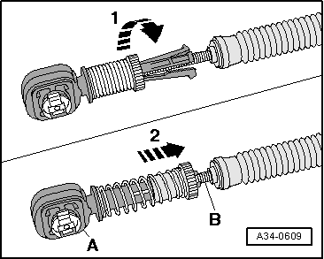
–  Pull forward the locking mechanism at shift cable and at selector cable -A- as far as the stop in -direction of arrow 1-, then lock by turning to the left in -direction of arrow 2-.
  S34-1022
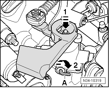
Fix the gearshift shaft as follows:
–  Press down the gearshift shaft in -direction of arrow 1-.
–  When pressing down the gearshift shaft turn angle lever -A- in -direction of arrow 2- and at the same time press it in direction of the gearshift shaft until it locks into the gearshift shaft.
Vehicles Octavia II
  N34-10319
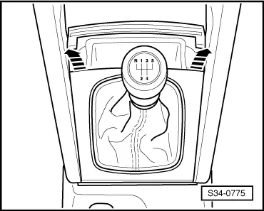
–  Lever the collar upwards and out of centre console cover -arrows-.
–  If present, detach the noise insulation.
Now fix the gearshift lever as follows:
  S34-0775
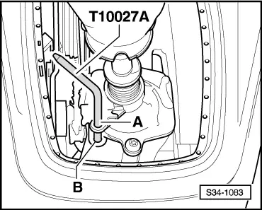
–  Insert the rig pin -T10027A -.
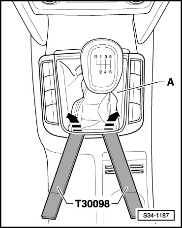
Vehicles Superb II
  S34-1083
–  Lever the collar upwards and out of centre console cover with release tool -T30098--arrows-.
–  Pull the collar upwards over the gearshift knob.
–  If present, detach the noise insulation.
Now fix the gearshift lever as follows:
–  Engage neutral position on gearshift lever.
  S34-1187
–  Insert the rig pin -T10027A-.
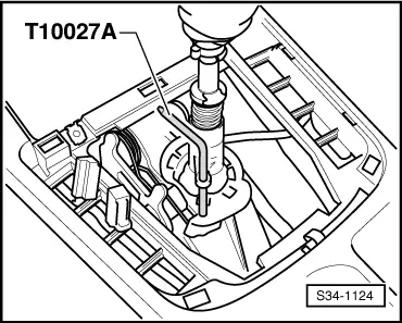
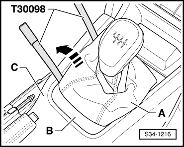
Vehicles Yeti
  S34-1124
–  Lever the collar -A- together with the surround -B- off the centre console -C- using the release tool -T30098--direction of arrow-.
–  Pull the collar upwards over the gearshift knob.
Now fix the gearshift lever as follows:
  S34-1216
–  Insert the rig pin -T10027A-.
Continued for all vehicles
  S34-1083
–  Ensure that the selector and shift cable -B- are pushed free of tension into the catches -A-.
–  Turn the locking mechanism at the shift cable and at the selector cable to the right as far as the stop -direction of arrow°1-.
The spring pushes the locking mechanism into the initial position -direction of arrow 2-.
  Note
The shift cable is now adjusted.
  A34-0609
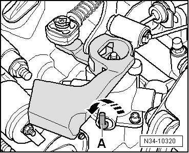
–  Turn the angle lever -A- back to the initial position -in direction of arrow-.
  Note
The angle lever -A- must be pressed out of the shift housing up to the stop and must point vertically upwards.
–  Pull out the rig pin - T10027A-.
–  If present, install the noise insulation.
–  Press collar into the cover.
–  Install air filter → Engine; Rep. gr.24.
  N34-10320

Functional test > < Removing and installing shift cable and selector cable|Install