| –
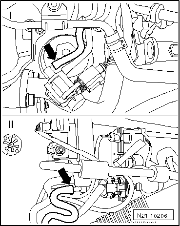
| Detach the hose on the middle connection of the exhaust gas recirculation radiator change-over valve -N345--arrow-. |
| –
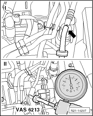
| Attach the hand vacuum pump -VAS 6213- to the detached hose and generate a vacuum of 0.06 MPa (0.6 bar). |
| –
| Observe the pressure gauge of the hand vacuum pump for approx. 30 seconds. |
| l
| The vacuum must not drop. |
| –
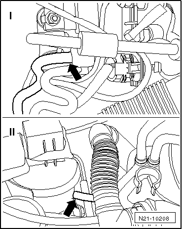
| Detach the vacuum hose on the vacuum setting element for switching over the radiator for exhaust gas recirculation. |
| –
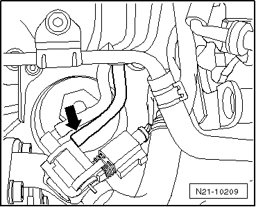
| Attach the hand vacuum pump -VAS 6213- with the factory-delivered test hose to the vacuum setting element and generate a vacuum of 0.06 MPa (0.6 bar). |

Note | t
| The adjustment on the vacuum setting element must be noticeable and the vacuum must not drop. If this is not the case, replace the radiator for exhaust gas recirculation (Fabia II, Roomster, Rapid) → Chapter, (Octavia II, Superb II, Yeti) → Chapter. |
| t
| If no defect can be found on the vacuum setting element, replace the vacuum line of the changeover valve for radiator of exhaust gas recirculation -N345-. |
|
|
|
 Caution