
Octavia Mk2
| Parts of cooling system engine side - Engines with identification characters CCSA, CHGA, CMXA |
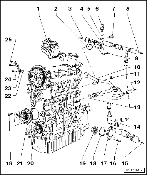
| 1 - | Throttle valve control unit -J338- |
| q | warmed up through coolant |
| 2 - | Sealing ring |
| q | replace |
| 3 - | to heat exchanger |
| q | connection diagram for coolant hoses → Chapter |
| 4 - | Connection fittings |
| 5 - | O-ring |
| q | replace |
| 6 - | Coolant temperature sender -G62- |
| q | for engine control unit |
| q | before removing, reduce pressure in cooling system if necessary |
| 7 - | Retaining clip |
| 8 - | towards top radiator |
| 9 - | 10 Nm |
| 10 - | Coolant pipe |
| 11 - | 40 Nm |
| 12 - | Hose to the expansion reservoir |
| 13 - | Sealing ring |
| q | replace |
| 14 - | Heating element for engine preheating -Z97- |
| q | is mounted in the engines with identification characters CCSA, CMXA |
| q | removing and installing → Chapter |
| 15 - | Bottom coolant hose |
| q | connection diagram for coolant hoses → Chapter |
| 16 - | 15 Nm |
| 17 - | Connection fittings |
| q | disassembling and assembling → Chapter |
| 18 - | O-ring |
| q | replace |
| 19 - | Coolant regulator |
| q | removing and installing → Chapter |
| q | check: heat up regulator in a water bath |
| q | Start of opening approx. 87 °C |
| q | End of opening approx. 102 °C |
| q | opening stroke at least 7 mm |
| 20 - | O-ring |
| q | replace |
| 21 - | Coolant pump |
| q | check smooth operation |
| q | replace completely if damaged or leaking |
| q | removing and installing → Chapter |
| 22 - | O-ring |
| q | replace |
| 23 - | Vent connection |
| q | to coolant expansion reservoir |
| 24 - | 10 Nm |
| 25 - | 10 Nm |