
Octavia Mk2
| Crankshaft - Summary of components |

| 1 - | Thrust washers |
| q | for bearing 3 |
| q | Fitting position: Oil grooves point to the crank webs |
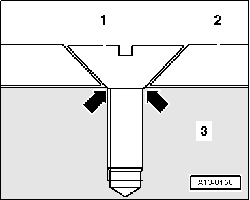
| 2 - | Bearing shell |
| q | for cylinder block with lubricating groove |
| q | do not mix up used bearing shells (mark) |
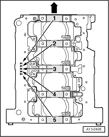
| q | insert new bearing shells for cylinder block with correct identification → Fig. |
| q | pay attention to locating element |
| 3 - | Sprocket |
| q | for oil pump drive |
| q | removing and installing → Chapter |
| 4 - | Crankshaft |
| q | Axial play when new: 0.07 ... 0.23 mm; Wear limit: 0.30 mm |
| q | Crankshaft bearing pins: Ø 48,00 mm |
| q | Conrod bearing pin: Ø 42,00 mm |
| 5 - | Bearing shell |
| q | for bearing cap without lubricating groove |
| q | do not mix up used bearing shells (mark) |
| q | The crankshaft bearing shells in the bearing caps are only supplied as replacement parts with the colour coding „yellow“ |
| q | pay attention to locating element |
| 6 - | 40 Nm + torque a further 90° (1/4 turn) |
| q | replace |
| 7 - | Bearing caps |
| q | Bearing cap 1: belt pulley side |
| q | Fitting position: retaining lugs of the bearing shells of the cylinder block/bearing cap must be on top of one another |
| 8 - | 10 Nm + torque a further 90° (1/4 turn) |
| q | replace |
| q | replace sensor rotor each time the bolts are slackened → Fig. |
| 9 - | Rotor |
| q | for engine speed sender -G28- |
| q | Installation is only possible in one position through offset holes |
| q | replace the sensor rotor each time the bolts are slackened |
| q | removing and installing → Fig. |
| 10 - | Needle bearing |
| q | only mounted on vehicles with automatic gearbox |
| q | Pull out the needle bearing for the crankshaft and drive it in → Chapter |
 Note
Note
|
|
| Letter on the cylinder block | Colour of the support | |
| B | = | blue |
| G | = | yellow |
| W | = | white |
Note
|