
Octavia Mk2
 Note
Note
|
|
|
|
|
|
|
 WARNING
|
|
|
|
|
|
Note
|

|
| Component | Nm |
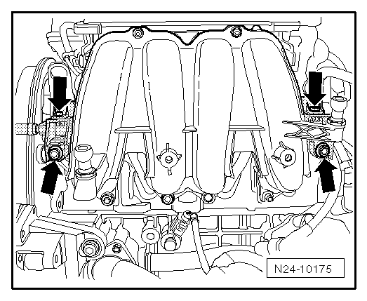
| Intake manifold to cylinder head | 25 |
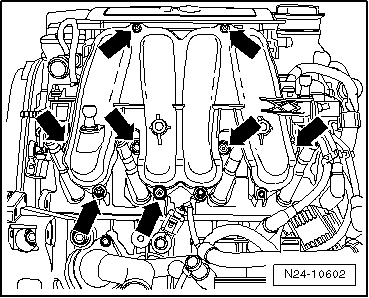
| Connecting screws of top part/bottom part of intake manifold | 3 |
| Petrol fuel distributor to intake manifold | 8 |
|
 Caution