skoda Workshop Repair Guides

Skoda Workshop Service and Repair Manuals

Removing and installing Hall senderG40 > < Removing
Install
Install
  Note
t  There must not be any oil or coolant present in the threaded holes for the cylinder head bolts.
t  Replace cylinder head screws, self-locking nuts and all the screws which have been tightened to a torquing angle.
t  Always replace gasket rings and seals.
t  Remove the new cylinder head gasket from its wrapping immediately before fitting.
t  Treat the seal with the utmost care. Damage to the silicone layer and in the area of the bead results in leakages.
t  When installing an exchange cylinder head with the camshafts installed, it is necessary to oil the contact surfaces between the roller arms and the cams after installing the cylinder head.
t  Secure all hose connections with corresponding hose clips.
  WARNING
Wear protective gloves when working with sealant and grease remover!
  Note
Make sure that when cleaning the cylinder head and cylinder block no foreign bodies can get into the cylinder, the oil and coolant galleries or into the threaded holes.
–  Carefully remove old sealant residue from the cylinder head and cylinder block using a chemical sealant remover.
–  Remove the crankshaft arrester -T10050- before placing on the cylinder head and turn the crankshaft in the opposite direction of rotation of engine until all the pistons are almost evenly positioned at the same height.
   
–  Pay attention to the identification of the cylinder head seal.
t  Part number -arrow 1-
t  Control code -arrow 2- (ignore)
t  Bores -arrow 3-
  Note
t  Install a new cylinder head gasket with the same marking, irrespective of whether or not the cylinder head was replaced.
t  If parts of the crankshaft drive were replaced, then the new cylinder head gasket must be redefined by measuring the protrusion of the piston in TDC → Chapter.
–  Position the cylinder head gasket with the marking to the top.
  S15-0438
–  For centering, screw in guide bolts -MP1-208 (3070)- into the outer holes on the suction side.
  Note
The tensioning pulley for timing belt must be fitted onto the pin screws when placing on the cylinder head.
–  Fit on cylinder head, insert all 8 cylinder head bolts and tighten by hand.
–  Screw the guide bolts out of the screw holes with a bolt tightener from -MP1-208 (3070)- and screw in the 2 remaining cylinder head screws.
  N15-0255
–  Tighten cylinder head screws in the order -1...10- in 4 stages as follows:
  S15-0530
StageProcedure
I
–  Pre-tighten with the torque wrench to 30 Nm.
II
–  Pre-tighten with the torque wrench to 50 Nm.
III
–  Using a rigid wrench torque a further 90° (1/4 turn).
IV
–  Using a rigid wrench torque a further 90° (1/4 turn).

  Note
Tightening up the cylinder head bolts after doing repair work is not necessary.
Further installation occurs in reverse order, while paying attention to the following:
–  Attach rear toothed belt guard at cylinder head.
–  Install the hub and the camshaft sprocket.
–  Lock the camshaft and the high pressure pump with the rig pins for diesel injection pump -3359-.
   
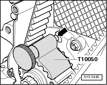
–  Rotate the crankshaft in direction of rotation of engine on TDC and lock the crankshaft with the crankshaft arrester -T10050-.
–  Fit on the toothed belt → Chapter.
–  Install cylinder head cover → Chapter.
  Note
If the cylinder head was replaced, refill the entire system with coolant.
–  Top up coolant → Chapter.
–  Filling and bleeding the fuel system. For this purpose, connect the vehicle diagnosis, measurement and information system -VAS 505X- and carry out the targeted function „bleeding the fuel system“. During this function, the fuel pump is actuated for 180 seconds.
–  Check fuel system for tightness → Chapter.
–  Perform a test drive, interrogate fault memory of engine control unit and erase → Vehicle diagnostic tester.
  Note
After deleting the fault memory of the engine control unit the readiness code must be checked, if necessary re-generated → Vehicle diagnostic tester.
  N15-0446

Removing and installing Hall senderG40 > < Removing