skoda Workshop Repair Guides

Skoda Workshop Service and Repair Manuals

Brake, brake mechanics > < Connection of the brake lines from the master brake cylinder to the hydraulic unit ABS BOSCH 8.2
Removing and installing control unit and hydraulic unit ABS BOSCH 8.2
Removing
Special tools and workshop equipment required
t  Brake pedal load, e.g. -V.A.G 1869/2-
t  Repair kit for plugs -1H0 698 311 A-
Fitting position:
The control unit is bolted to the hydraulic unit and is located on the right of the engine compartment.
  Caution
The brake lines around the hydraulic unit must not be bent!
–  Disconnect battery → Electrical System; Rep. gr.27.
–  Remove engine cover → engine; Rep. gr.10.
For vehicles with 1.4 ltr. engine:
–  Detach the hose between the non-return valve and the camshaft housing.
Vehicles with engines TDI CR DPF (diesel particle filter)
–  Remove engine cover.
–  Remove the cooling water tank cover → Body Work; Rep. gr.66.
   
–  Disconnect plug -1...4- for diesel particle filter and lambda probe.
–  Remove the holder with the plug from the bulkhead plenum chamber and lay to the side.
–  Pull the engine control unit out of the bracket and lay to the side.
–  Remove engine control unit bracket.
–  Remove the insulation from the bulkhead plenum chamber.
–  Remove partition panel → Body work; Rep. gr.66.
Continued for all vehicles
  N26-10416
–  Press down the red fuse -arrow-.
  N45-10062
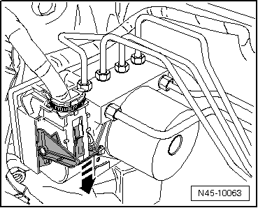
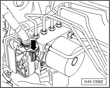
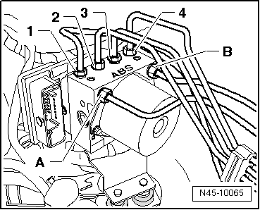
–  Unlock the plug connection of the control unit -arrow- and pull out towards the front.
–  Insert brake pedal load, e.g. -V.A.G 1869/2-
–  Press brake pedal and lock in place with brake pedal load, e.g. -V.A.G 1869/2-, at least 60 mm.
–  Attach the bleeder hose of the bleeding bottle onto the vent valve of the front left brake caliper and open bleeder valve.
–  Shut the vent valve once the brake fluid flowed out.
–  Disconnect the bleeder hose from the vent valve.
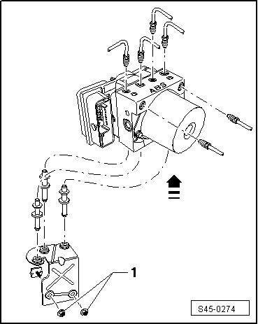
–  Place sufficient non-fluffing cloths under the control unit and the hydraulic unit.
Make sure that no brake fluid gets onto the contacts of the plug connections.
–  Mark the brake lines of the hydraulic unit -A and B- to the master brake cylinder.
  N45-10063
–  Unscrew the brake lines of the hydraulic unit and of the master brake cylinder, unclip from the bracket and lay to the side.
–  Close the brake lines and threaded holes immediately with plugs from the repair kit -1H0 698 311 A-.
–  Mark the remaining brake lines (to brake calipers) -1...4-, unscrew from the hydraulic unit and seal off.
  N45-10065
–  Pull hydraulic unit with control unit upwards and out of the bracket.
–  Slacken nuts -1- and remove bracket (if it is necessary to remove the bracket).
Install
  Note
t  New hydraulic control units are filled with brake fluid and pre-bled.
t  Only then remove plugs from the new hydraulic unit when the relevant brake line is installed.
t  If the plugs were already removed from the hydraulic unit before the brake line is installed, then brake fluid may escape and adequate filling and bleeding can no longer be guaranteed.
t  When installing, pay attention that the rubber bearings are not pressed out of the bracket.
–  Further installation occurs in reverse order.
–  Make sure that the multi-pin connector latches correctly with the ABS control unit -J104-.
–  Remove brake pedal load, e.g. -V.A.G 1869/2-.
–  Bleeding brake system → Chapter.
–  Code new ABS control unit -J104- → Vehicle diagnostic tester and adapt.
–  Connect the battery and carry out any additional measures after reconnecting the battery → Electrical System; Rep. gr.27.
Tightening torques:
  S45-0274
Bolt to hydraulic unit8 Nm
Nuts to body20 Nm
 
Brake lines to ABS unit: 
Thread M 10 x 114 Nm
Thread M 12 x 114 Nm


Brake, brake mechanics > < Connection of the brake lines from the master brake cylinder to the hydraulic unit ABS BOSCH 8.2