skoda Workshop Repair Guides

Skoda Workshop Service and Repair Manuals

Removing and installing the cylinder head|Install > < Removing and installing the cylinder head
Removing
Removing
Observe all safety measures and notes for assembly work on the fuel supply and injection system, at the charge air system and observe as well the rules for cleanliness → Chapter.
Observe the instructions for the fuel hose in the engine compartment → Chapter.
–  Remove left charge air pipe → Chapter.
–  Remove the plenum chamber cover and partition panel → Body work; Rep. gr.66.
–  Remove vacuum line from the brake servo unit.
–  Drain coolant → Chapter.
   
–  Screw out screws -arrows- and remove pulsation dampener -2-.
  A21-10478
–  Disconnect plug -1- at oil pressure switch -F1-.
–  Detach vacuum line -2- and release screw -arrow- of vacuum line.
  A15-10799
–  Disconnect plug -4- at the coolant temperature sender -G62-.
  A19-10975
–  Remove the coolant hoses from the connection fitting, to do so slacken the hose clamps -1- and -2-
Left-hand drive
–  Release screw -2-.
  A19-10975
–  Slacken screw -3- and swivel the bracket towards the front.
–  Remove warm-type clamp -1- between pre-exhaust pipe and exhaust turbocharger.
Right-hand drive
  N26-10608
–  Remove warm-type clamp -2- between pre-exhaust pipe and exhaust turbocharger.
Continued for all vehicles
–  Remove the sound dampening system → Body Work; Rep. gr.50.
  N26-10516
–  First release the screws -1-, then unscrew the nuts -2-.
–  Remove bracket for pre-exhaust pipe.
–  Tie up the loosened pre-exhaust pipe at the bulkhead plenum chamber.
  N26-10535
–  Release screws of coolant return-flow line -arrows- and lay the coolant return-flow line to the side.
  Note
Collect the fuel which flows out with a cleaning cloth.
  N23-10365
–  Detach fuel hoses -2 and 5-. To do so, push the quick couplings onto the nozzles, press in the securing elements (hold pressed) and detach the quick couplings.
–  Remove cylinder head cover → Chapter.
  Note
Collect the fuel which flows out with a cleaning cloth.
  S10-0440
–  Remove high pressure line -2- between fuel distributor and high pressure pump.
  N23-10355
–  Unclip the engine pre-wiring from the holder -arrow-.
–  Disconnect all the remaining plug connections at the engine.
–  Lay the engine pre-wiring to the side.
  N15-10501
–  Release screw -arrow- for oil dipstick.
  N15-10599
–  Remove the connection pipes -A- for exhaust gas recirculation.
  Note
Collect the escaping engine oil with the old oil collecting and suction equipment -V.A.G 1782-.
  N15-10443
–  Slacken union nut -1- with open ring spanner 17 mm-A-.
–  Release screws -2, 3, 5 and 6-.
–  Remove oil feed line -7-.
–  Remove the support for exhaust turbocharger -4- from the oil return-flow line -8-.
  S21-0153
–  Disconnect the plug -arrow- from the Hall sender -G40-.
–  Remove the toothed belt from the camshaft sprocket and from the toothed belt gear of the high pressure pump → Chapter „Removing and installing toothed belt“.
  N15-10598
–  Screw out the fixing screws -1- of the camshaft sprocket.
–  Remove camshaft sprocket from the hub.
  N15-10498
–  Counterhold the hub with the counterholder -T10051- and slacken the fixing screw -1- of the hub.
–  Unscrew the fixing screw of the hub by approx. 2 turns.
  N15-0271
–  Position the extractor -T10052- and align it with the hub bores.
–  Tighten fixing screws -1-.
–  Slacken the hub of the toothed belt sprocket from the camshaft cone by uniformly tightening the screw of the extractor -2-.
  Note
Hold the extractor firmly using a wrench SW 30.
–  Remove hub from cone of camshaft.
  N15-0280
–  Unscrew the fixing screw -arrow- of the rear toothed belt guard.
  N15-10499
–  Unscrew nut -1- for tensioning pulley.
  N15-10332
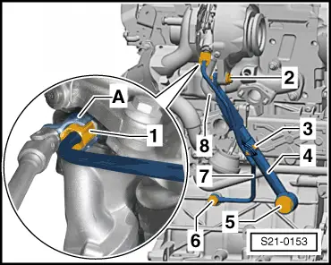
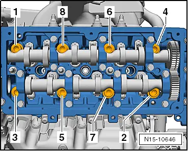
–  Follow the sequence -1 … 8- for loosening the cylinder head screws.
–  Release cylinder head screws.
  Note
t  The assistance of a second mechanic is required for removing the cylinder head.
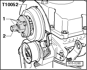
t  
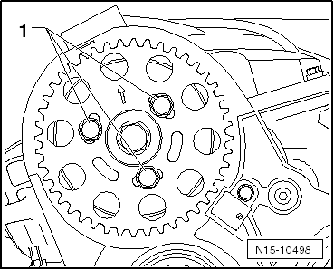
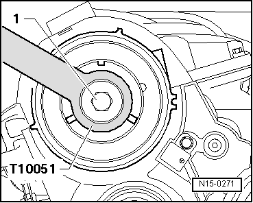
The timing belt tensioning pulley is removed from the pin screw when lifting out the cylinder head.
–  First of all raise the cylinder head on the gearbox side and thread it out of the rear toothed belt guard. Make sure that the timing belt tensioning pulley does not fall down.
  Caution
Risk of damage to the glow plugs when placing down the cylinder head.
If the cylinder head is removed with installed glow plugs, do not place it down on the sealing surface since the glow plugs protrude slightly beyond the sealing surface.
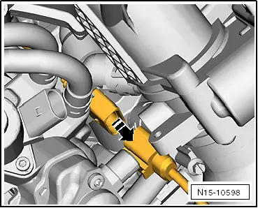
–  Place down the cylinder head in such a way that the oil return flow line does not bend, if necessary place a wooden wedge under the exhaust manifold.
  N15-10646

Removing and installing the cylinder head|Install > < Removing and installing the cylinder head