
Roomster

| 1 - | 20 Nm + torque a further 90° (1/4 turn) |
| q | replace |
| q | pay attention to sequence for loosening and tightening → Chapter |
| 2 - | Valve-lever shaft |
| q | do not interchange |
| 3 - | Cylinder head bolt |
| q | replace |
| q | pay attention to sequence for loosening and tightening → Chapter |
| q | before fitting insert washers (Pos. 4) in the cylinder head |
| 4 - | Washer |
| q | for cylinder head screws |
| q | insert in cylinder block before fitting the bearing cap |
| 5 - | Bucket tappets |
| q | do not interchange |
| q | with hydraulic valve clearance compensation |
| q | lay aside with contact surface facing down |
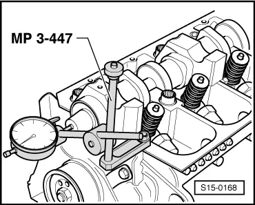
| q | before installing check axial play of the camshaft → Fig. |
| q | oil contact surfaces |
| q | before removing remove the camshaft bearing shells |
| 6 - | Valve collets |
| 7 - | Valve spring retainer |
| 8 - | Valve spring outside |
| q | removing and installing: |
| t | Cylinder head removed: with -MP 1-206 (3047 A)-, -MP 1-211 (VW 541/1a,/5)-, -MP 1-213 (2036/1)- |
| t | Cylinder head fitted → Chapter |
| 9 - | Valve spring inside |
| q | removing and installing: |
| t | Cylinder head removed: with -MP 1-206 (3047 A)-, -MP 1-211 (VW 541/1a,/5)-, -MP 1-213 (2036/1)- |
| t | Cylinder head fitted → Chapter |
| 10 - | Valve stem seal |
| q | replace → Chapter |
| 11 - | Valve guide |
| q | check → Chapter |
| 12 - | The unit injector |
| q | removing and installing → Chapter |
| 13 - | Cylinder head |
| q | pay attention to note → Chapter |
| q | reworking valve seats → Chapter |
| 14 - | Sealing ring |
| q | Neither oil nor grease sealing lip of sealing ring |
| q | before installing, remove with a clean cloth oil residues from camshaft studs |
| q | before fitting, cover slot on the camshaft cone with adhesive tape (e.g. Scotch tape) |
| q | removing and installing → Chapter |
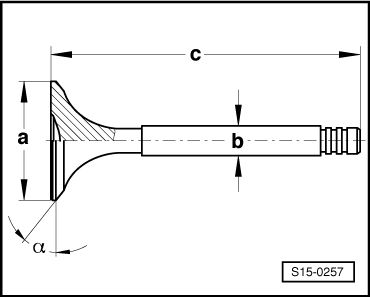
| 15 - | Valves |
| q | Valve dimensions → Fig. |
| 16 - | Bearing shell |
| q | do not mix up used bearing shells (mark) |
| q | ensure the retaining lugs are correctly located in the bearing caps and in the cylinder head |
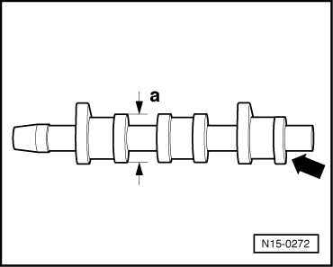
| 17 - | Camshaft |
| q | Inspecting axial play → Fig. |
| q | removing and installing → Chapter |
| q | Slack: max. 0.01 mm |
| q | Identification, timing → Fig. |
| 18 - | Bearing caps |
| q | Mounting sequence → Chapter |
| q | Bearing cap 4 is identified like bearing cap 5. |
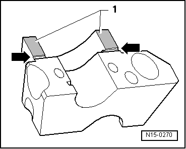
| q | for installing seal the separator surfaces of bearing caps 1 and 4 with sealant -AMV 174 004 01- → Fig. |
| 19 - | 8 Nm + torque a further 90° (1/4 turn) |
| q | replace |
|
|
 Note
Note
|
|
Note
|
|
| Dimension | Inlet valve | Exhaust valve | |
| Ø a | mm | 35,95 | 31,45 |
| Ø b | mm | 6,980 | 6,956 |
| c | mm | 89,95 | 89,95 |
| α | ∠° | 45 | 45 |
|
|
| 3. Cylinder -arrow- | 858 C |