skoda Workshop Repair Guides

Skoda Workshop Service and Repair Manuals

Exhaust system > < Testing components
Check fuel pressure senderG247
Check fuel pressure sender -G247-
Special tools and workshop equipment required
t  Assembly device -T10118-
t  Open ring spanner with 3/8" drive, SW 27 mm
t  
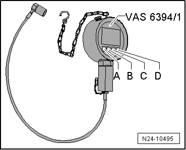
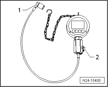
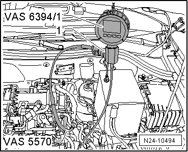
Pressure sensor tester, e.g. -VAS 6394- (includes digital manometer -VAS 6394/1-)
t  
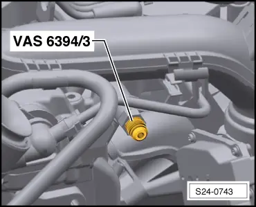
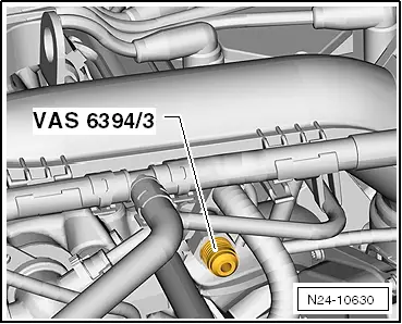
Adapter, e.g. -VAS 6394/3-
t  
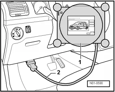
Test adapter, e.g. -VAS 5570-
  WARNING
The injection system consists of a high pressure part (max. pressure of 12 MPa = 120 bar) and a low pressure part (pressure of approx. 0.6 MPa = 6 bar).
Before opening the high pressure area, e.g. removing the high pressure pump, the fuel distributor, the injection valves, the fuel pipes or the fuel pressure sender -G247-, the fuel pressure in the high pressure area with a remaining pressure of approx. 0.6 MPa (6 bar) must be reduced. The procedure for this is described in the chapter „release pressure in the high pressure area of the fuel system“ → Chapter.
Work procedure
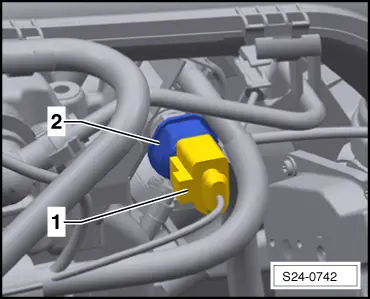
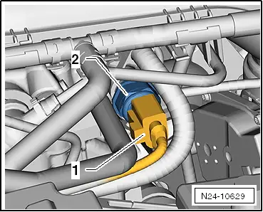
–  Disconnect plug -1- and remove fuel pressure sender -G247--2-.
   
For the vehicles Fabia II, Roomster
  S24-0742
For the vehicles Octavia II, Yeti
–  Moisten the sealing cone of the adapter -VAS 6294/3- with clean engine oil and screw it into the fuel distributor.
  N24-10629
For the vehicles Fabia II, Roomster
  S24-0743
For the vehicles Octavia II, Yeti
Continued for all vehicles
   Tightening torque: 22 Nm
  N24-10630
–  Release the screw plug -2- and screw the fuel pressure sender -G247- into the tester -VAS 6394/1-.
   Tightening torque: 22 Nm
–  Connect the pressure line -1- of the digital manometer -VAS 6394/1- onto the adapter -VAS 6394/3-.
  N24-10400
–  Connect the test adapter -VAS 5570- to the fuel pressure sender -G247--1- and to the engine plug.
  N24-10494
–  Switch on the tester -VAS 6394/1 -, for this step, briefly press the button -A- once.
  Note
t  If the button -A- is pressed for 2 seconds, the illumination is switched on for 20 seconds.
t  If the tester -VAS 6394/1- does not indicate 0 MPa (0 bar), carry out a zero point of the balance by means of the → operating instructions.
  N24-10495
–  Connect the vehicle diagnosis, measurement and information system -VAS 505X--1- to the diagnostic connection.
–  Switch on ignition.
–  On the display press consecutively the following buttons:
Vehicle self-diagnosis
Self-diagnosis
01 - Engine Electronics
011 - Measured values
–  Select measured value block 140 and confirm with Q.
The actual value which is transmitted to the vehicle by the fuel pressure sender -G247- is shown in the display field 3.
–  Start engine.
–  Compare the displayed pressure on the digital manometer -VAS 6394/1- with the actual value on the vehicle diagnosis, measurement and information system -VAS 505X-.
l  The pressures may deviate maximum 0.5 MPa (5 bar) from one another.
If the deviation is greater than 0.5 MPa (5 bar):
–  Perform a vehicle diagnosis, measurement and information system -VAS 505X- of the guided function „remove high fuel pressure“.
–  Replace fuel pressure sender -G247-.
–  Repeat the test with the new fuel pressure sender -G247- and compare both measured values.
If the measured values do not correspond again:
–  Perform a cable testing → Vehicle diagnostic tester.
  N01-0590

Exhaust system > < Testing components