skoda Workshop Repair Guides

Skoda Workshop Service and Repair Manuals

Disassembling and assembling engine > < Removing and installing V-ribbed belt
Install
Install
  Note
t  Adjusting work on the toothed belt must only be performed on a cold engine.
t  When rotating the camshaft, the crankshaft must not be positioned at TDC for any one piston. Risk of damaging valves and pistons.
Condition
l  Interlock camshaft with locking pin -3359- or -MP1-301-.
l  Interlock the crankshaft with the crankshaft arrester -T10100-.
l  Interlock tensioning pulley in released position with fixing nut.
   
–  Pay attention to the correct fitting of the tensioning pulley in the opening in the rear toothed belt guard -arrow-.
  S13-0450
–  Slightly screw in screws -arrows-.
l  It must still be possible to turn the camshaft sprocket on the hub, however it must not hang loose.
–  Turn camshaft sprocket clockwise in the elongated holes as far as the stop.
–  Fit toothed belt onto crankshaft toothed belt sprocket, tensioning pulley, camshaft and, last of all, onto the toothed belt sprocket of the coolant pump.
Adjust the tension of toothed belt as follows:
  S13-0459
–  Loosen the fixing nut -1- of the tensioning pulley.
–  Turn the eccentric of the tensioning pulley with offset screwdriver -T10264- clockwise -arrow- in such a way until the pointer -2- stands in the centre of the base plate in the gap.
  Note
Ensure that the fixing nut does not turn.
  A13-10263
–  Hold the eccentric of the tensioning pulley in this position and tighten the fixing nut to 20 Nm and torque a further 45° (1/8 turn).
  Note
When tightening the fixing nut, the pointer turns -arrow- max. 5 mm to the right from the gap of the base plate. This position must not be corrected, because the toothed belt settles when running-in.
  S13-0402
–  Position the counterholder -T10172- with the adapters -T10172/4- onto the toothed belt sprocket of the camshaft.
–  Push the counterholder in -direction of arrow- and keep it pretensioned.
–  Pre-tighten the screws -1- for the toothed belt sprocket of the camshaft in this position to 20 Nm.
  Note
The screws must be further turned according to the setting and inspection of the timing → Anchor.
–  Remove the locking pin -3359- and the crankshaft arrester -T10100-.
Test timing
–  Turn the crankshaft 2 turns in the direction of running of the engine until the crankshaft is positioned shortly before TDC for cylinder 1.
  A13-0814
–  Interlock during this motion the hub in the direction of running of the engine with locking pin -3359-.
–  Check whether:
  S13-0404
l  the crankshaft can be interlocked with the crankshaft arrester -T10100 -;
  N15-10174
l  the pointer of the tensioning pulley -2- stands in the centre or max. 5 mm to the right from the gap of the base plate (area -a-).
If the conditions are not fulfilled:
–  Correct timing → Anchor.
If the conditions are fulfilled:
–  Continued if the timing is correctly set → Anchor.
Correct timing
  S13-0271
–  Loosen bolts -arrows- of the camshaft sprocket.
  S13-0448
–  Rotate crankshaft in direction of rotation of engine until the crankshaft can be arrested with the crankshaft arrester -T10100-.
  Note
If the crankshaft can be turned via the TDC for cylinder 1, turn crankshaft back slightly and once again set to the TDC for cylinder 1 by turning in direction of rotation of engine.
  N15-10173
–  Position the counterholder -T10172- with the adapters -T10172/4- onto the toothed belt sprocket of the camshaft.
–  Push the counterholder in -direction of arrow- and keep it pretensioned.
–  Pre-tighten the screws -1- for the toothed belt sprocket of the camshaft in this position to 20 Nm.
  Note
The screws must be further turned according to the setting and inspection of the timing → Anchor.
Continued if the timing is correctly set
–  Remove the locking pin -3359- and the crankshaft arrester -T10100-.
–  Turn crankshaft 2 turns in the direction of running of the engine until the crankshaft is again on TDC.
–  Once again test timing → Anchor.
If the conditions are fulfilled:
–  Remove the locking pin -3359- and the crankshaft arrester -T10100-.
  A13-0814
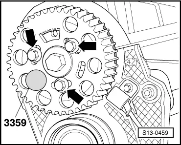
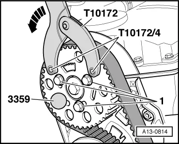
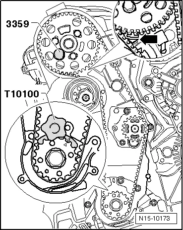
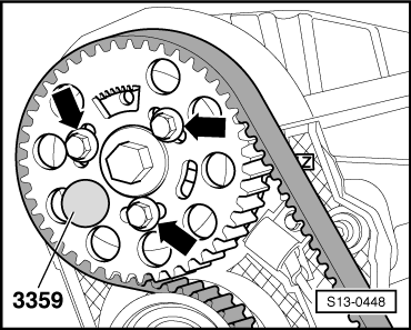
–  Torque the fixing screws -arrows- of the camshaft sprocket a further 45° (1/8 turn) using a rigid wrench. While doing so, counterhold the belt pulley with the counterholder -T10172- with adapters -T10172/4-.
The further assembly is carried out in the reverse order, while paying attention to the following:
–  Install the bottom timing belt guard and the belt pulley/vibration damper.
–  Install middle timing belt guard.
–  Screw tensioning pulley lever of V-ribbed belt on compact holder.
–  Install the fan wheel on the visco fan coupling → Chapter.
–  Install top toothed belt guard.
–  Fit the ribbed V-belt → Chapter.
–  Install the lock carrier → Body Work → Rep. Gr.50.
–  Inspect headlight beam setting and adjust if necessary → Superb.
  WARNING
When undertaking all assembly work, particularly in the engine compartment due to its cramped construction, please observe the following:
t  Lay lines of all kinds (e.g. for fuel, hydraulic fluid, cooling fluid and refrigerant, brake fluid, vacuum) and electrical lines in such a way that the original line guide is re-established.
t  Ensure that there is adequate free access to all moving or hot components.
  S13-0448

Disassembling and assembling engine > < Removing and installing V-ribbed belt