
Drive shaft for Yeti power transmission gearbox 02Q
 Note
Note| Insert all bearings on the drive shaft with gear oil. |
| For vehicles Octavia II |

| 1 - | Circlip |
| q | removing and installing → Chapter |
| 2 - | Washer |
| q | Outer diameter = 78.6 mm |
| q | can only be used on modified gearbox housings (as of production date 04.06 up to 01.08) → Chapter |
| q | assign components via → Electronic Catalogue of Original Parts |
| 3 - | Gearbox housing |
| q | adapted for the washers Pos. 2 and Pos. 4 as of production date 04 06 up to production date 01.08 in the area of the bearing pedestal for the grooved ball bearing Pos. 6 → Chapter |
| q | flattened parts at the grooved ball bearing and at the bearing pedestal of the grooved ball bearing as of production date 02.08 → Chapter |
| q | assign components via → Electronic Catalogue of Original Parts |
| 4 - | Washer |
| q | Outer diameter = 85 mm |
| q | can only be used on modified gearbox housings (as of production date 04.06 up to 01.08) → Chapter |
| q | assign components via → Electronic Catalogue of Original Parts |
| 5 - | Circlip |
| q | determine → Fig. when replacing the grooved ball bearing -Pos. 6- and the drive shaft -Pos. 8- |
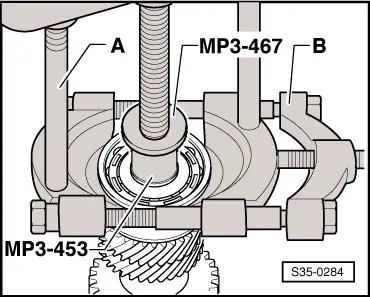
| 6 - | Grooved ball bearing |
| q | always replace → Electronic Catalogue of Original Parts |
| q | flattened parts at the grooved ball bearing and at the bearing pedestal of the grooved ball bearing as of production date 02.08 → Chapter |
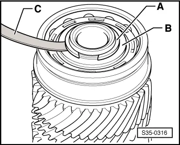
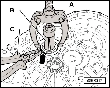
| q | remove → Fig. |
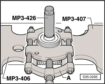
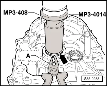
| q | pressing on → Fig. |
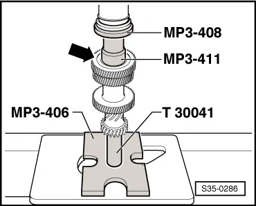
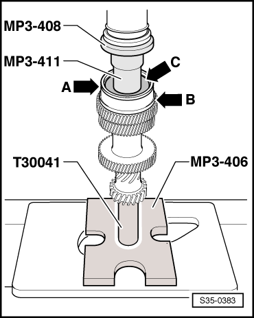
| 7 - | 5th gear pinion |
| q | pressing off → Fig. |
| q | Fitting position: round groove -arrow- points to the grooved ball bearing Pos. 6 |
| q | pressing on → Fig. |
| 8 - | Drive shaft |
| q | with 3rd/4th gear pinon and 6th gear |
| 9 - | Cylindrical-roller bearing |
| q | with circlip |
| q | removing → Fig. |
| q | installing → Fig. |
| q | Fitting position: the circlip in the bearing points towards the drive shaft |
| 10 - | Clutch housing |
|

| 1 - | Circlip |
| q | removing and installing → Chapter |
| 2 - | Gearbox housing |
| 3 - | Circlip |
| q | determine → Fig. when replacing the grooved ball bearing -Pos. 4- and the drive shaft -Pos. 6- |
| 4 - | Grooved ball bearing |
| q | always replace → Electronic Catalogue of Original Parts |
| q | remove → Fig. |
| q | pressing on → Fig. |
| 5 - | 5th gear pinion |
| q | remove → Fig. |
| q | Fitting position: round groove -arrow- points to the grooved ball bearing Pos. 4 |
| q | pressing on → Fig. |
| 6 - | Drive shaft |
| q | with 3rd/4th gear pinon and 6th gear |
| 7 - | Cylindrical-roller bearing |
| q | with circlip |
| q | removing → Fig. |
| q | pressing on → Fig. |
| q | Fitting position: the circlip in the bearing points towards the drive shaft |
| 8 - | Clutch housing |
|
|
|
|
|
|
|
Note
|
|
Note
|
|
| Measured value (mm) | Circlip thickness (mm) | Axial play (mm) |
| 0,01 … 0,05 | 1,86 | 0,01 … 0,05 |
| 0,05 … 0,07 | 1,89 | 0,01 … 0,05 |
| 0,07 … 0,10 | 1,92 | 0,01 … 0,05 |
| 0,10 … 0,13 | 1,95 | 0,01 … 0,05 |
| 0,13 … 0,16 | 1,98 | 0,01 … 0,05 |
|
|
|
|