skoda Workshop Repair Guides

Skoda Workshop Service and Repair Manuals

Charge air system with exhaust gas turbocharger > < Fuel tank and fuel delivery unit
Removing and installing exhaust gas turbocharger
Special tools and workshop equipment required
t  Hose clamps up to 25 mm -MP7-602 (3094)-
t  Pliers for spring strap clamps
t  Catch pan e.g. - VAS 6208-
t  Hot screw paste -G 052 112 A3-
  Caution
In case a mechanical damage to the exhaust gas turbocharger is found, e.g. damage to the compressor wheel, it is not sufficient to only replace the turbocharger. In order to avoid consequential damage, perform the following tasks:
t  Clean all oil lines.
t  Change engine oil and oil filter.
t  Inspect the air filter housing, the air filter element and the intake hoses for contaminations.
t  Inspect the whole charge-air routing and the charge air cooler for foreign bodies.
If foreign bodies are detected in the charge air system, the complete charge-air routing must be cleaned and if necessary the charge air cooler must also be replaced.
Removing
–  Remove engine cover → Chapter.
   
–  Remove the cover -1- for the connection fitting, to do so release the lateral retaining clasps -arrows-.
  A10-10945
–  Unclip connection fitting, to do so release retaining clasps -arrows-.
–  Remove connection fitting with air guide hose.
  A10-10946
–  Unplug the plug -1- from the turbocharger divert air valve -N249-.
–  Unhook the hoses -2- at the pressure pipe and open the wiring -3-.
  N15-10374
–  Detach the hoses -1- at the inlet connection of the turbocharger.
–  Unplug the plug -2- from the charge pressure sender -G31- with intake air temperature sender 2 -G299- and unscrew the fixing screws -3-.
  N21-10175
–  Press the retaining clips -1- towards the outside and pull the pressure pipe towards the top -2-.
–  Then pull off the pressure pipe -2- from the exhaust turbocharger.
  N21-10176
–  Release fixing screws -arrows- and remove the heat shield from the exhaust turbocharger.
  N21-10177
–  Pinch off coolant hoses with hose clamps -3094- as shown in the figure.
–  Place a catch pan under the engine.
–  Release screws -1, 3, 4, 5-.
–  Remove the coolant lines from the exhaust turbocharger and place them to the side.
–  Remove V-ribbed belt → Chapter.
–  Remove alternator → Electrical System; Rep. gr.27.
  A21-10242
–  Unscrew fixing nuts at turbocharger -arrows-.
  N21-10181
–  Expose cables -1- at catalytic converter.
–  Separate plug connections -2-.
–  Unscrew fixing nuts -3- and remove the seal.
–  Remove catalytic converter downwards.
  N21-10179
–  Unscrew the fixing screws -arrows- of the heat shield and pull off the panel in -direction of arrow- from the exhaust manifold.
–  Unscrew the fixing screws -1- of the oil feed pipe -3-.
  N21-10180
–  Unscrew the hollow screw -2- from the timing case and remove the coolant pipe.
–  Unscrew the fixing screw -4- and remove the bracket -5-.
  S21-0133
–  Unscrew the fixing screws -1- of the oil feed line -2- and remove the pipe.
  N21-10183
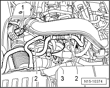
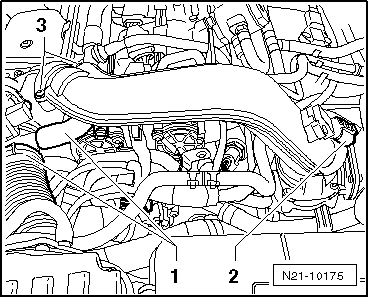
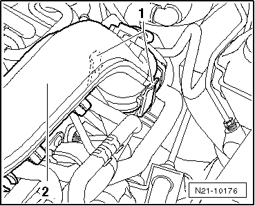
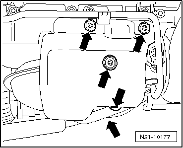
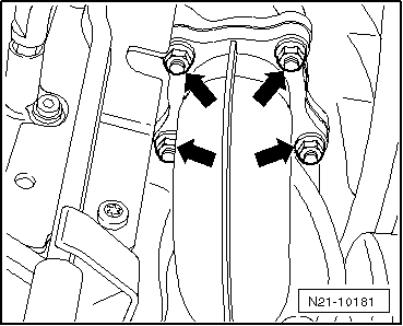
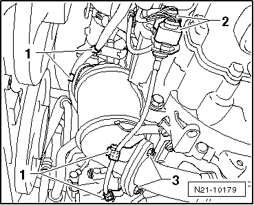
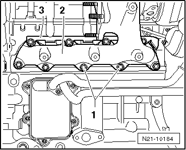
–  Unscrew all the fixing nuts of the exhaust manifold -1- and remove the bracket -3- from the stud bolts.
–  Remove exhaust manifold with turbocharger -2- from cylinder head.
  Note
The exhaust turbocharger can only be replaced with exhaust manifold and pressure unit.
Install
  Caution
In case a mechanical damage to the exhaust gas turbocharger is found, e.g. damage to the compressor wheel, it is not sufficient to only replace the turbocharger. In order to avoid consequential damage, perform the following tasks:
t  Clean all oil lines.
t  Change engine oil and oil filter.
t  Inspect the air filter housing, the air filter element and the intake hoses for contaminations.
t  Inspect the whole charge-air routing and the charge air cooler for foreign bodies.
If foreign bodies are detected in the charge air system, the complete charge-air routing must be cleaned and if necessary the charge air cooler must also be replaced.
Installation is performed in the reverse order, pay attention to the following points:
t  Gaskets, gasket rings and self-locking nuts must be replaced.
t  Coat the stud bolts at the cylinder head with hot bolt paste -G 052 112 A3- before installing.
t  Fill the exhaust turbocharger with engine oil at the connection fitting for the oil feed line.
t  After installing the turbocharger, run engine at idling speed for about 1 minute to ensure that oil is supplied to the turbocharger.
t  Secure all hose connections with hose clamps → Electronic Catalogue of Original Parts.
Tightening torques:
   Exhaust turbocharger - Summary of components → Chapter.
   Catalytic converter and component parts - Summary of components → Chapter.
–  Inspect coolant level, if necessary top up cooling system and bleed → Chapter.
  N21-10184

Charge air system with exhaust gas turbocharger > < Fuel tank and fuel delivery unit