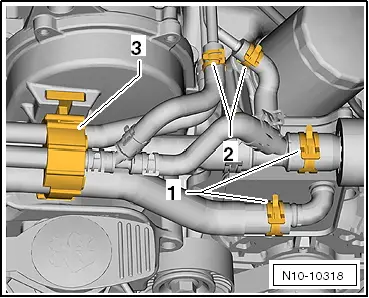
Slacken clamps -1- and -2- and detach coolant hoses.
–
Unlatch the clamp -3- and pull it towards the top with the coolant hoses.
–
Place the coolant hoses to the rear.
–
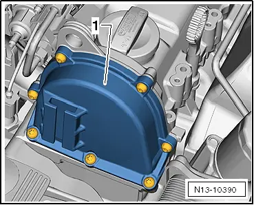
Unscrew fixing screws from top timing case -1-.
–
Remove timing case.
Install
Installation is performed in the reverse order, pay attention to the following points:
–
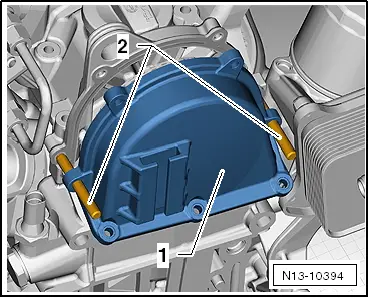
To better guide the timing case, screw two pin screws M6x70 -1- into the cylinder head cover.
WARNING
Wear protective gloves when working with sealant and grease remover!
–
Remove residual sealant from the sealing surfaces on the top timing case and at the cylinder head with chemical sealant remover.
–
Degrease the sealing surfaces.
–
Cut off nozzle tube at the front marking (Ø of nozzle approx. 3 mm).
Note
t
The installation procedure must not last longer than 6 minutes from the moment the sealant is applied until the moment the fixing screws are tightened to 8 Nm.
t
The sealant begins to harden after 6 minutes.
t
Ensure that the tightening process of the fixing screws is carried out in two steps.
–
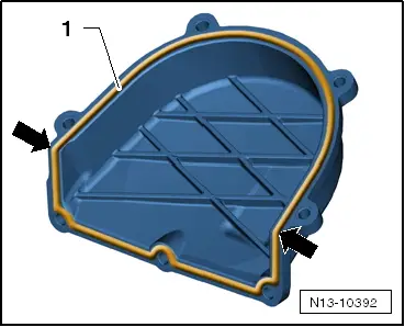
Apply sealant - D 176 501 A1- on the sealing surface -1-.
–
Apply a little more sealant in the area of the -arrows-.
–
Position the timing case -1- onto the pin screws -2-.
Slide the timing case -1- up to the stop onto the cylinder head cover.
Make sure that the timing case does not tilt.
–
Release the stud bolts and screw in the fixing screws by hand.
Stage l of the tightening process.
–
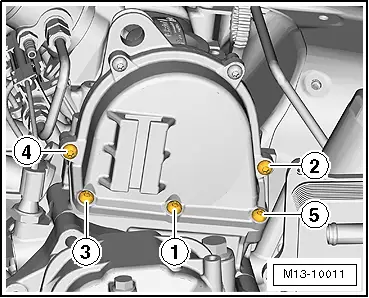
Tighten the fixing screws to 5 Nm in the specified order -1- to -5-.
Stage ll of the tightening process.
–
Tighten the fixing screws to 8 Nm in the specified order -1- to -7-.
–
Push the clamp -3- from above fully into the bracket.
–
Fit on the coolant hoses and attach the spring strap clamps -1- and -2-.
 Note
Note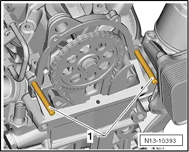
 WARNING