skoda Workshop Repair Guides

Skoda Workshop Service and Repair Manuals

Ignition system, glow plug system > < Checking change-over flap for radiator for exhaust gas recirculation
Removing and installing pre-exhaust pipe with diesel particle filter
Engines with identification characters CFFB, CFGB, CFHA, CFHC, CFHF, CFJA
Special tools and workshop equipment required
t  Ratchet ring wrench -T10384-
t  Ring spanner set for lambda probe
t  Set of tools -T10395-
t  Transport security -T10404-
t  Hot screw paste -G 052 112 A3-
Removing
–  Remove assembly carrier with steering gear → Chassis; Rep. gr.40.
   
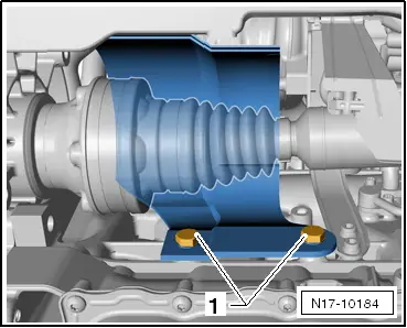
–  Unscrew screws -1- of protective plate for right drive shaft, if present.
–  Remove drive shaft to the right → Chassis; Rep. gr.40.
–  Remove engine cover → Chapter.
  N17-10184
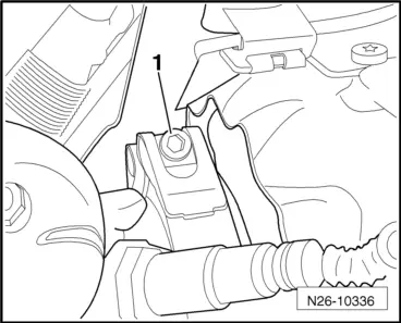
–  Remove warm-type clamp -1- between diesel particle filter and exhaust turbocharger.
  N26-10336
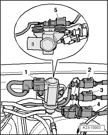
–  Disconnect the following plug connections:
t  Position 2: exhaust gas temperature sender 4 -G648- (orange)
t  Position 4: lambda probe -G39- (black)
t  Position 5: exhaust gas temperature sender 3 -G495- (brown)
  A23-10003
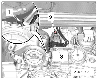
–  Remove lambda probe -G39--3-.
  A26-10721
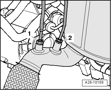
–  Unscrew the exhaust gas temperature sender 4 -G648--1- from the pre-exhaust pipe using the socket insert SW 17 mm from the set of tools -T10395-.
  A26-10189
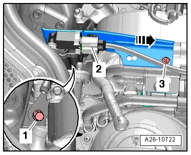
–  Disconnect plug -2- at differential pressure indicator -G505-.
–  Screw out screw -3- and remove bracket with differential pressure indicator -G505- from the bracket of the additional fuel pump in -direction of arrow-.
–  Remove the differential pressure sender -G505- from the bracket with the hoses connected → Chapter.
  Caution
Risk of damage!
The differential pressure sender -G505- is very sensitive and therefore it must be treated with utmost care. It must not touch somewhere when laying it down.
–  Attach the differential pressure sender -G505- to the diesel particle filter with the hoses connected.
  A26-10722
–  Unscrew the screw -1- of the bracket at the cylinder head.
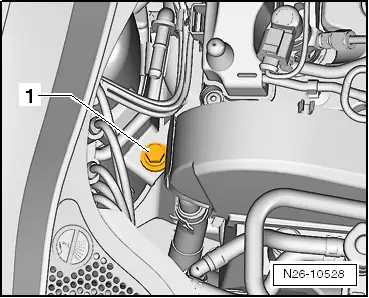
–  Slacken the clamping sleeve and slide it backwards.
  N26-10528
–  Unscrew nuts -1- using the ratchet ring wrench -T10384-.
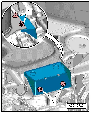
–  Release nuts -2- and remove bracket for pre-exhaust pipe.
  Note
t  The assistance of a second mechanic is required for removing the pre-exhaust pipe.
t  The decoupling element in the pre-exhaust pipe should not be bent by more than 10° - risk of damage.
  A26-10723
t  Secure the decoupling element with the transport security -T10404- against overtensioning -arrow-.
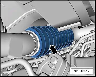
  N26-10517
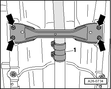
–  Remove tunnel bridge -arrows-.
–  Remove diesel particle filter downwards.
Install
  Note
t  The decoupling element in the pre-exhaust pipe should not be bent by more than 10° and over-tensioned - risk of damage.
t  Secure the decoupling element against damage by means of the transport security -T10404-.
Installation is performed in the reverse order, pay attention to the following points:
t  Replace gasket and fixing clamp for pre-exhaust pipe.
t  Tightening torques → Chapter.
–  First fasten the pre-exhaust pipe loosely to the exhaust gas turbocharger and then fasten to the bottom bracket.
–  Align exhaust system free of stress:
t  Octavia II → Chapter
t  Superb II, Yeti → Chapter
After replacing the diesel particle filter, the adaptation of the ash mass balance must be set to „0“ → Vehicle diagnostic tester.
  A26-0734

Ignition system, glow plug system > < Checking change-over flap for radiator for exhaust gas recirculation