
ForTwo L3-1.0L (2009)
Auxiliary Input / Output Jack: Procedures
AZ82.60-P-0001-01MCC Retrofit iPod interface wiring harness
AZ82.60-P-0001-01MCC Retrofit IPod Interface Wiring Harness
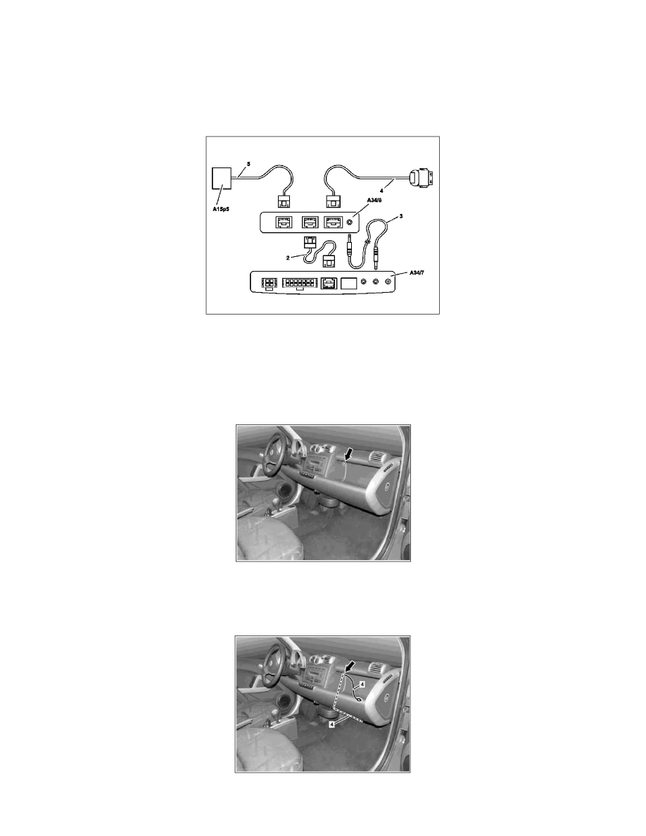
Connection diagram
2
Electrical line
3
Electrical line
4
Electrical wiring harness for iPod adapter
5
Electrical wiring harness for display (Bluetooth hands-free system)
A15p5 Display
A34/7
Bluetooth module
A34/8
iPod adapter
1
Drill hole with diameter of 9 mm, as shown, at instrument panel (arrow).
Cordless drill/driver
gotis://G_58.0_01.1
Ensure that the components behind this are not damaged as otherwise these must be replaced.
2 Lead electrical wiring harness for iPod adapter (4) through the hole (arrow) and route in the front passenger footwell as shown.