
ForTwo L3-1.0L (2009)
Hydraulic Control Assembly - Antilock Brakes: Locations
GF42.50-P-4001MCC Traction System Hydraulic Unit, Component Description
1
Hydraulic unit
N47-5
ESP control unit
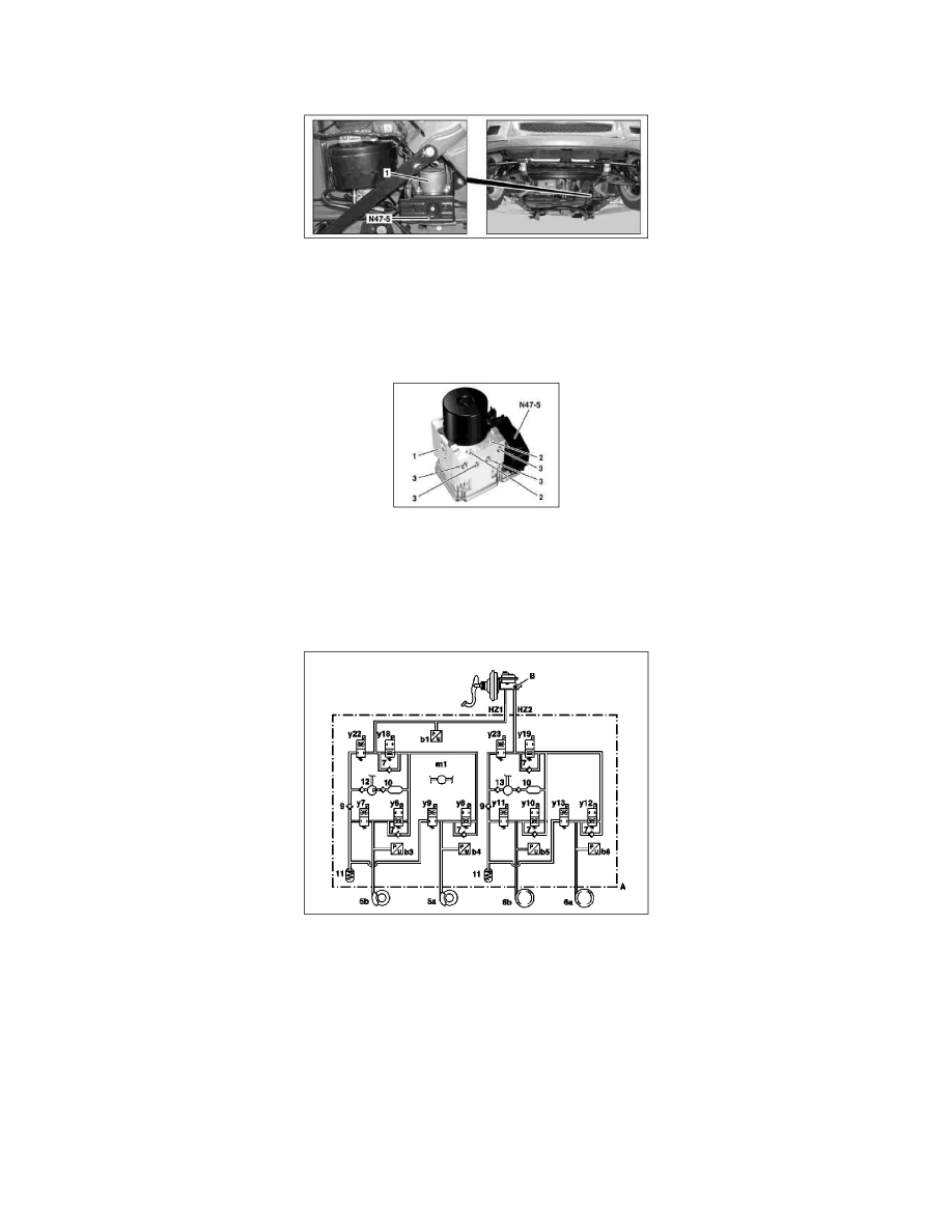
Location
The hydraulic unit is located on the vehicle underfloor.
1
Hydraulic unit
2
Inlet of tandem master brake cylinder
3
Outlet to respective brake caliper or wheel brake cylinder
N47-5
ESP control unit
Function diagram
5a
Front wheel brake, right
5b
Front wheel brake, left
6a
Rear wheel brake, right
6b
Rear wheel brake, left
7
Check valve
9
Check valve of return pump
10
Damper
11
Low-pressure reservoir
12
Self-priming pump (front axle)
13
Self-priming pump (rear axle)
b1
Front axle brake pressure sensor
b3
Left front pressure sensor