
ForTwo L3-1.0L (2009)
4
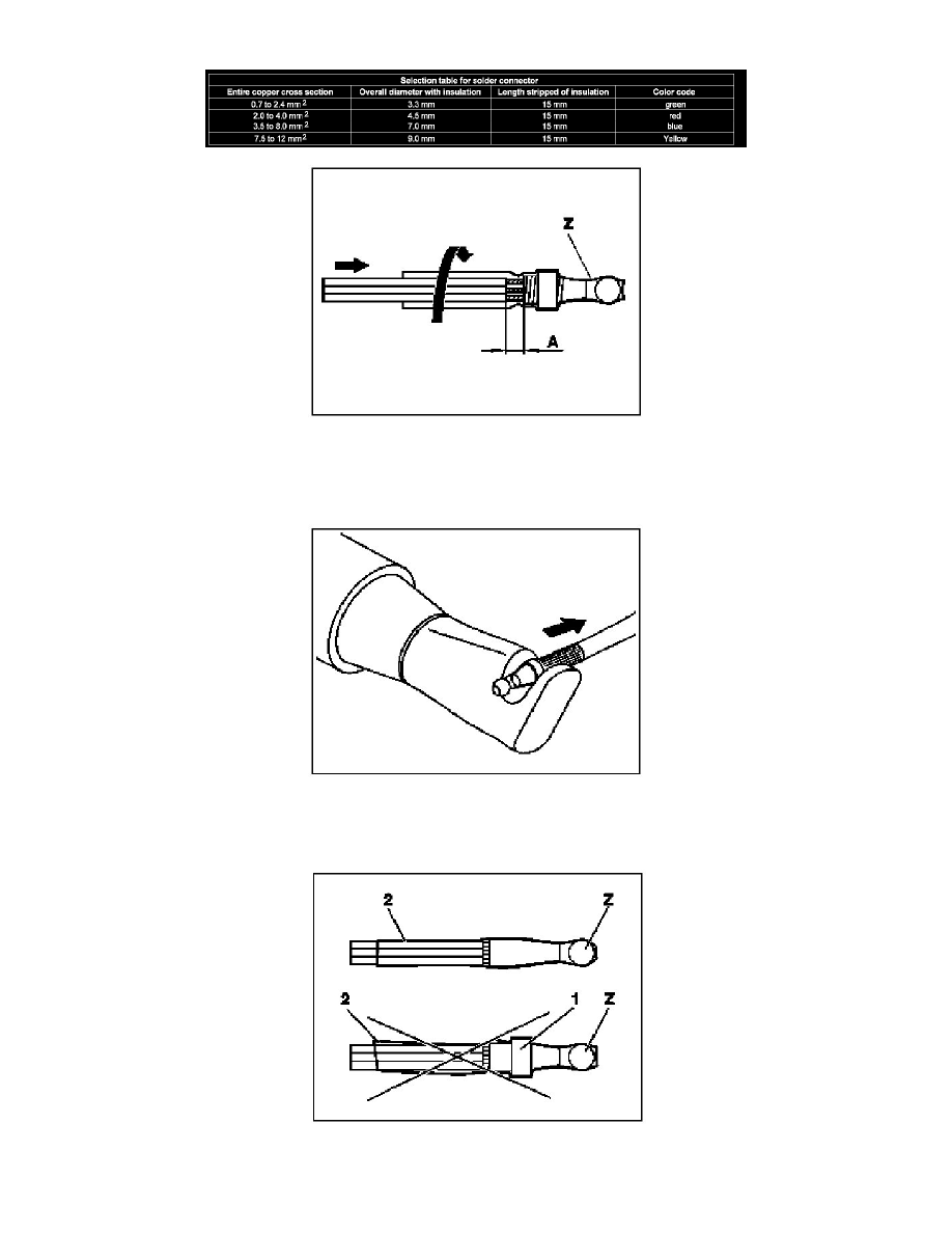
Select solder connector according to table below.
5
Insert the cables into the corresponding solder connections (Z) according to the total cable cross-section.
A maximum of seven individual cables may be inserted into each solder connection (Z).
6
Ensure that solder connection (Z) is fully rotated onto cables.
Approx. 5 mm (A) of the stripped line ends should be visible.
7
Heat solder connector with hot air gun (approx. 400 °C). Hot air blower
gotis://E_15.54_12.0
Start at tapered end until soldering ring dissolves and covering has completely wrapped itself around the lines.
8
Check soldered point.
The soldering ring (1) of the solder connection (Z) must no longer be visible. The jacketing (2) must make contact with the lines as shown.