
ForTwo L3-1.0L (2009)
4
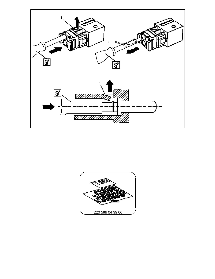
Insert blade holder with clamping pliers and RK 2.5 solder contact blade from rear side into cable duct of connector.
Align sleeve of RK 2.5 solder contact blade to spring shackle (1) of connector housing.
This step presses on the spring shackle (1) of the connector.
5
Remove contact pin together with blade holder with clamping pliers and RK 2.5 solder contact blade from connector by gently pulling towards
rear.
AR00.19-P-0120-19A Remove contacts from laminated contact system coupling
AR00.19-P-0120-19A Remove Contacts From Laminated Contact System Coupling
220 589 04 99 00, New passenger vehicle wiring harness repair kit