
ForTwo L3-1.0L (2009)
Knock Sensor: Description and Operation
GF07.04-P-6030MCC Component Description For The Knock Sensor
ENGINE 132.9 in MODEL 451.3 /4
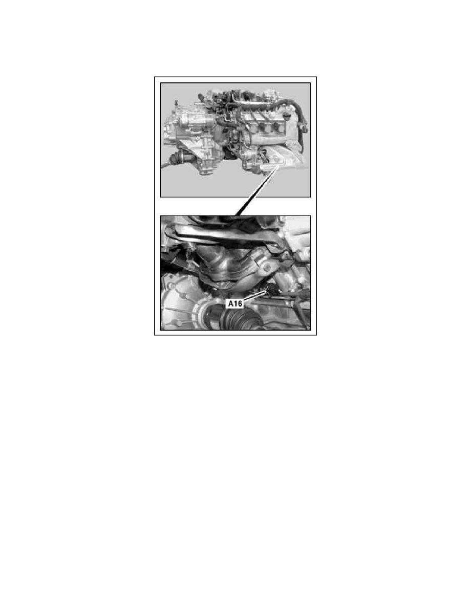
A16 Knock sensor
Location
The knock sensor is located on the engine crankcase under the exhaust manifold.
Task
The knock detects vibrations which are emitted by the cylinders and transmits these in the form of an electrical signal to the ME-SFI [ME] control unit
(N3/10).
In the event of failure of the knock sensor, the ignition performance map for low quality fuels or fuels with a low octane rating is used by the ME control
unit.
Design
The knock sensor consists of:
^
A seismic mass
^
Piezoceramic perforated disc
^
Thrust sleeve
^
Housing
Function
The knock sensor is screwed through the thrust sleeve to the crankcase. The vibrations which are coming from the individual combustion chambers are
transmitted by the seismic ground to the piezoceramic perforated disc. The piezoceramic generates an electrical voltage signal and passes this on to the
ME-SFI [ME] control unit.