
ForTwo L3-1.0L (2009)
Oxygen Sensor: Description and Operation
GF07.04-P-6100MCU Component Description For O2 Sensor
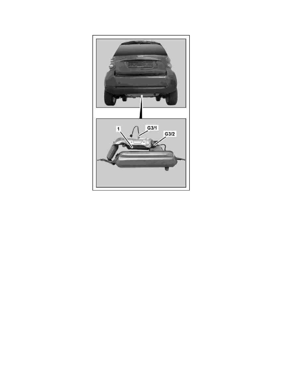
1
Three-way catalytic converter
G3/1
O2 sensor downstream from catalytic converter
G3/2
O2 sensor upstream TWC
Location
The O2 sensor upstream of TWC is located in the exhaust system upstream of the three-way catalytic converter. The O2 sensor downstream of TWC is
located in the exhaust system downstream of the three-way catalytic converter.
Task
The O2 sensors detect the residual oxygen content in the exhaust and transmit this as a voltage signal to the ME-SFI [ME] control unit (N3/10).
Body
Installed O2 sensors are voltage planar sensors. The sensor tip consists of a gas-tight ceramic (zirconium dioxide) which is coated on both sides with a
porous platinum layer. Both platinum layer are connected together and act as electrodes.
Function
The outer sides of the O2 sensors lie in the exhaust flow while the inner sides aerated with oxygen in the air. For a rich mixture the oxygen concentration
in the exhaust drops a lot and generates a sensor voltage of about 0.8 V. The ME-SFI [ME] control unit (N3/10) regulates the fuel quantity until the
value jumps back again.
For a lean mixture the process operates in reverse, the voltage drops to about 0.2 V. This process is repeated once a second. In order to reach the
operating temperature of about 300°C as quickly as possible the O2 sensors have an integral heater which is controlled by the ME-SFI [ME] control unit.