
ForTwo L3-1.0L (2009)
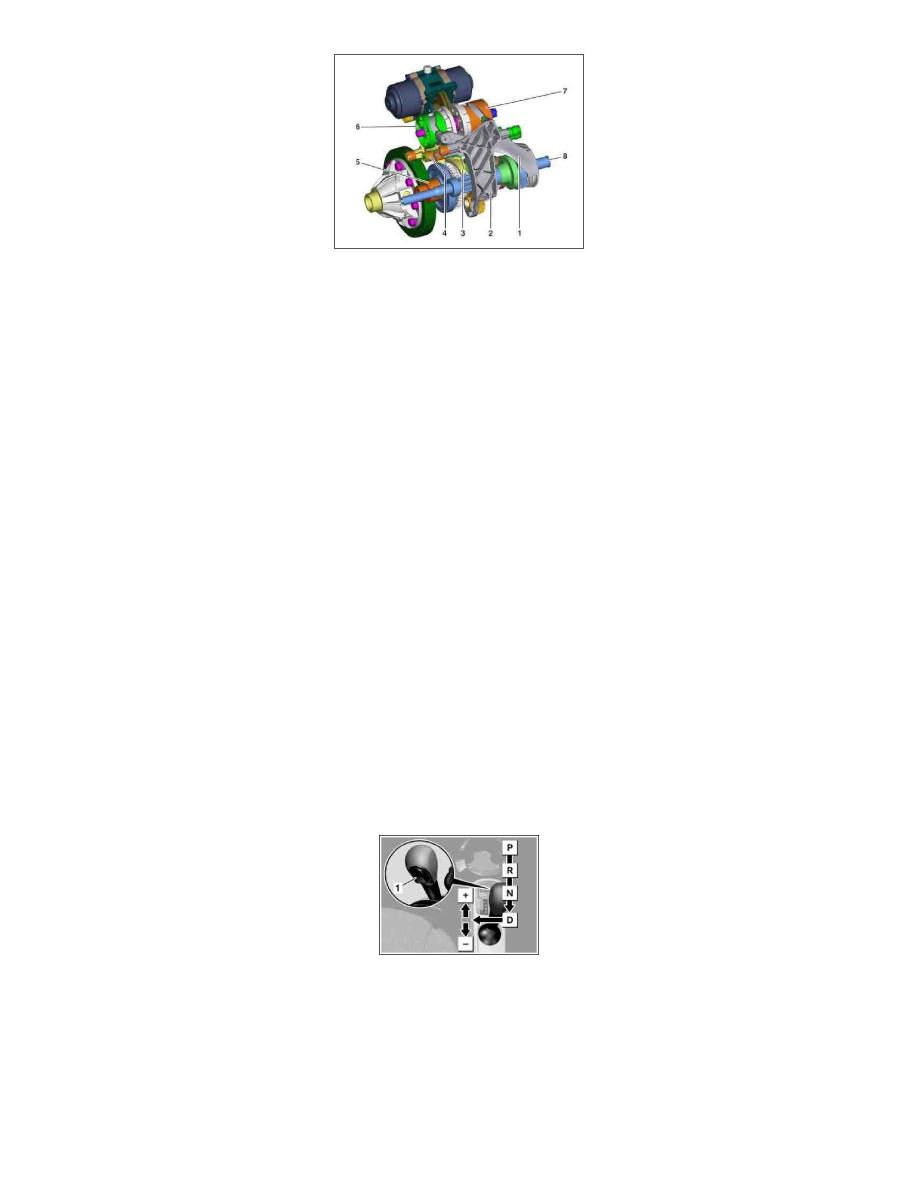
1
Shift fork, shift collar 5
2
Shift fork for sliding gear, reverse gear
3
Shift fork for shift collar 1/3
4
Shift fork for shift collar 2/4
5
Main shaft
6
Selector drum 1/3, 5
7
Selector drum 2/4, R
8
Input shaft
Function
The shift forks are displaced by the selector drums parallel to the transmission shafts. They in turn slide the shift collars on the input shaft or the main
shaft towards the respective idler gears.
The actuation of the shift forks is conducted by two independent selector drums, each of which has a groove. The sliding blocks for two shift forks run in
each groove:
Selector drum 1/3, 5:
^
Sliding block of shift fork for shift collar 1/3
^
Sliding block of shift fork, shift collar 5
Selector drum 2/4, R:
^
Sliding block of shift fork for shift collar 2/4
^
Sliding block of shift fork for sliding gear, reverse gear
The positions of both sliding blocks in the same groove are offset to each other by 120°. If a sliding block shifts a shift fork out of the center position, the
other sliding block is located in the straight area of the groove (in the center position of the associated shaft fork).
GF26.00-P-0003-01MCU Automated Manual Transmission Shift Lever
GF26.00-P-0003-01MCU Automated Manual Transmission Shift Lever Positions
Shift diagram
1
Park pawl button
P
Park position
R Reversing position
N Neutral position
D Drive position
+
Manual upshift
-
Manual downshift
Possible positions:
^
The mechanical park pawl is engaged in the park position, the display "P" appears in the multifunction display (A1p13) of the instrument cluster