
ForTwo L3-1.0L (2009)
The sliding blocks in the grooves of the selector drum are in the neutral position. No gear is engaged.
Reverse gear
The selector drum 2/4, R rotates through 120° downwards. This deflects the upper sliding block by 22.5 mm to the left.
The sliding gear of reverse gear engages in the external toothing of the shift collar 1/3
The sliding blocks in the selector drum 1/3, 5 are in the neutral position.
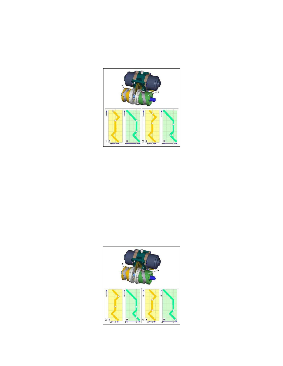
Shift position of 1st gear (1) and 2nd gear (2)
a
Selector drum 1/3, 5
b
Selector drum 2/4, R
c
Adjustment of selector drum (1 grid = 40°)
d
Deflection of sliding block mass (1 grid = 7.5 mm)
1st gear
The selector drum 1/3, 5 rotates downwards by 40°. This displaces the upper sliding block by 7.5 mm to the left. The shift collar 1/3 is slid into the idler
gear of first gear. The sliding blocks in the selector drum 2/4, R are in the neutral position.
2nd gear
When changing from 1st gear to 2nd gear both selector drums are twisted upwards by 40°. This in turn displaces the lower sliding block for the selector
drum 2/4, R by 7.5 mm to the left. The shift collar 2/4 is slid into the idler gear of second gear. The sliding blocks of the selector drums 1/3, 5 are in the
neutral position.
Shift position of 3rd gear (3) and 4th gear (4)
a
Selector drum 1/3, 5
b
Selector drum 2/4, R
c
Adjustment of selector drum (1 grid = 40°)
d
Deflection of sliding block mass (1 grid = 7.5 mm)