
Brat F4-1781cc 1.8L (1982)
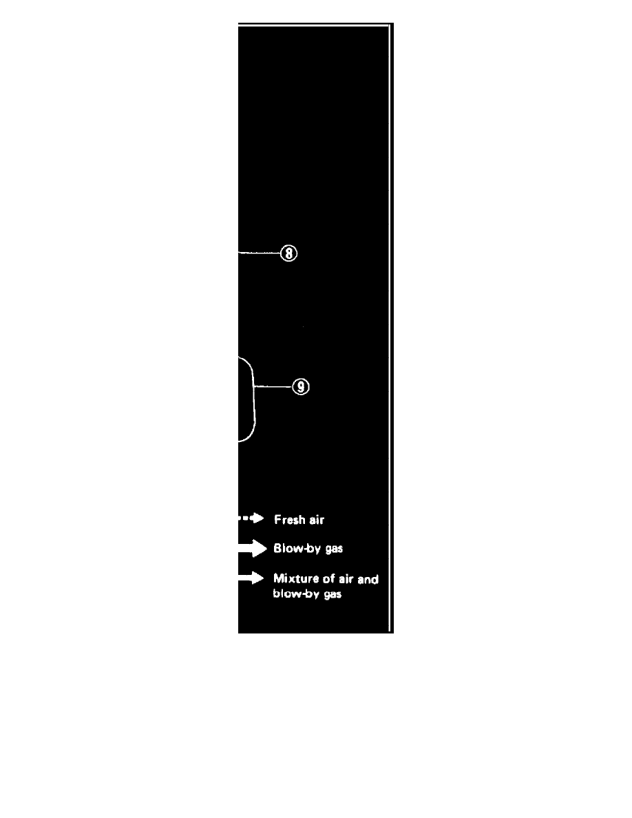
Fig.30 - Positive Crankcase Ventilation System
This system, Fig. 30, prevents emission of blow-by gases from crankcase into atmosphere. At part-throttle operation, blow-by gases flow from
crankcase through connecting hose on 2-4 rocker cover to PCV valve, which is operated by manifold vacuum, and into intake manifold. Ambient
air is drawn through air cleaner and into crankcase via connecting hose on 1-3 rocker cover. Ambient air then combines with blow-by gases and
enters intake manifold.
During wide open throttle operation manifold vacuum is not sufficient to allow all of the blow-by gases to enter intake manifold so excess blow-by
gas enters air cleaner through connecting hose on 1-3 rocker cover where it is drawn into carburetor.
Under some driving conditions, oil from crankcase will blow through connecting hose of 24 rocker cover and could be drawn into intake manifold
by force of vacuum. A connecting hose from air cleaner to connecting hose on 24 rocker cover prevents this by reducing vacuum.