
Forester F4-2.5L DOHC Turbo (2007)
4) Perform the ABS sequence control.
5) When the VDCH/M begins to work, check the following working sequence.
(1) FL wheel performs decompression, holding, and compression in sequence, and subsequently FR wheel repeats the cycle.
(2) RR wheel performs decompression, holding, and compression in sequence, and subsequently RL wheel repeats the cycle.
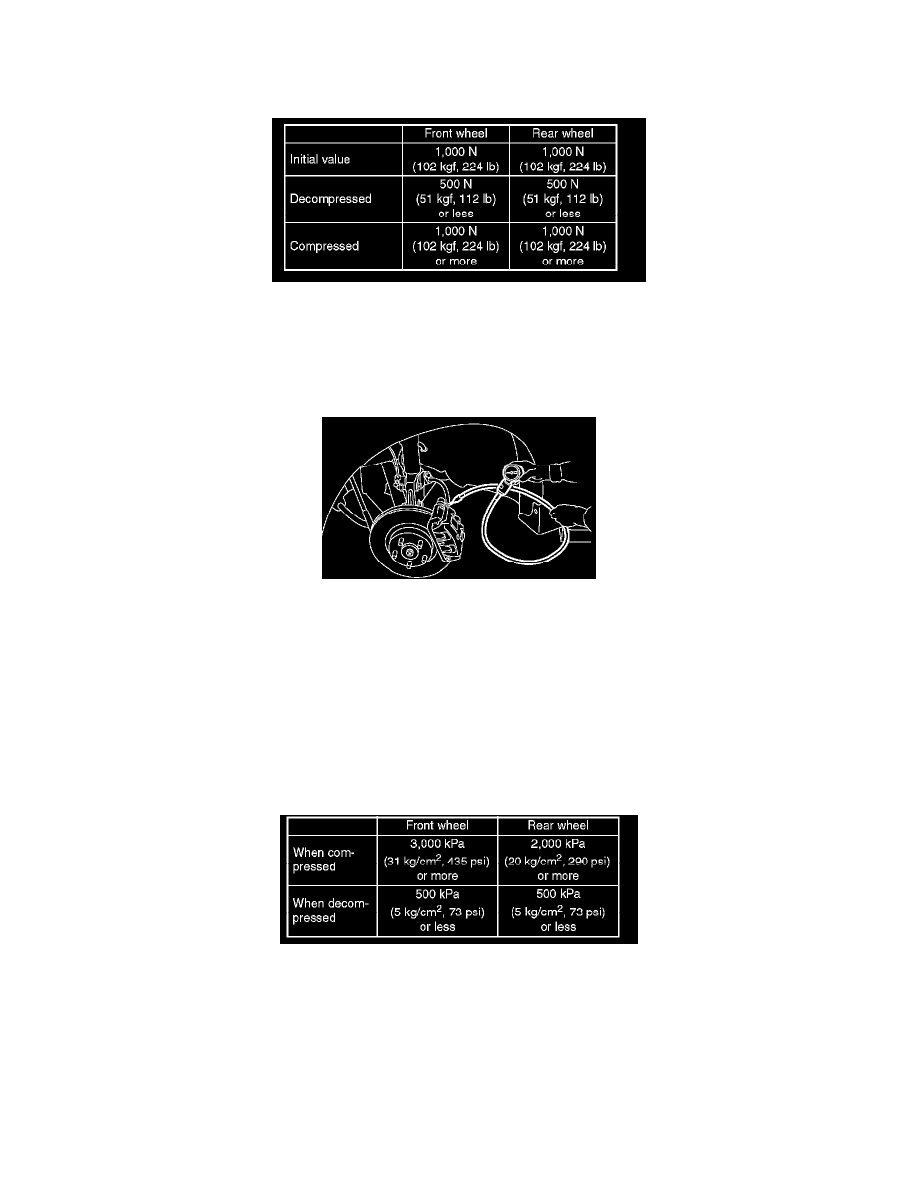
6) Read values indicated on the brake tester and check if fluctuation of values meet the standard values when decompressed and compressed.
7) After checking, also check if any irregular brake pedal tightness is felt.
CHECKING THE VDC HYDRAULIC CONTROL MODULE (VDCH/M) VDC OPERATION BY PRESSURE GAUGE
1) Lift-up the vehicle and remove the wheels.
2) Disconnect the air bleeder screws from FL and FR caliper bodies.
3) Connect two pressure gauges to the FL and FR caliper bodies.
CAUTION:
^
Pressure gauges used exclusively for brake fluid must be used.
^
Do not employ a pressure gauge previously used for transmission; the piston seal is expanded and may lead to malfunction of the brake.
NOTE: Wrap a sealing tape around pressure gauge.
4) Bleed air from the pressure gauges.
5) Perform the VDC sequence control.
6) When the VDCH/M begins to work, and first FL side performs holding, decompression, and compression, and then FR side performs
decompression, holding, and compression.
7) Read values indicated on the pressure gauge and check if the fluctuation of values between decompression and compression meets the standard
values. Also check if any irregular brake pedal tightness is felt.
8) Remove the pressure gauges from FL and FR caliper bodies.
9) Install the air bleeder screws to FL and FR caliper bodies.
10) Remove the air bleeder screws from RL and RR caliper bodies.
11) Connect two pressure gauges to the RL and RR caliper bodies.
12) Bleed air from the pressure gauges and RL, RR caliper bodies.
13) Perform the VDC sequence control.
14) When the hydraulic unit begins to work, at first RR side performs holding, decompression, and compression, and then RL side performs holding,
decompression, and compression.
15) Read values indicated on the pressure gauges and check if they meet the standard value.