
Forester F4-2.5L SOHC (2004)
6) Connect the brake pipes to master cylinder.
7) Connect the electric connector for brake fluid level indicator.
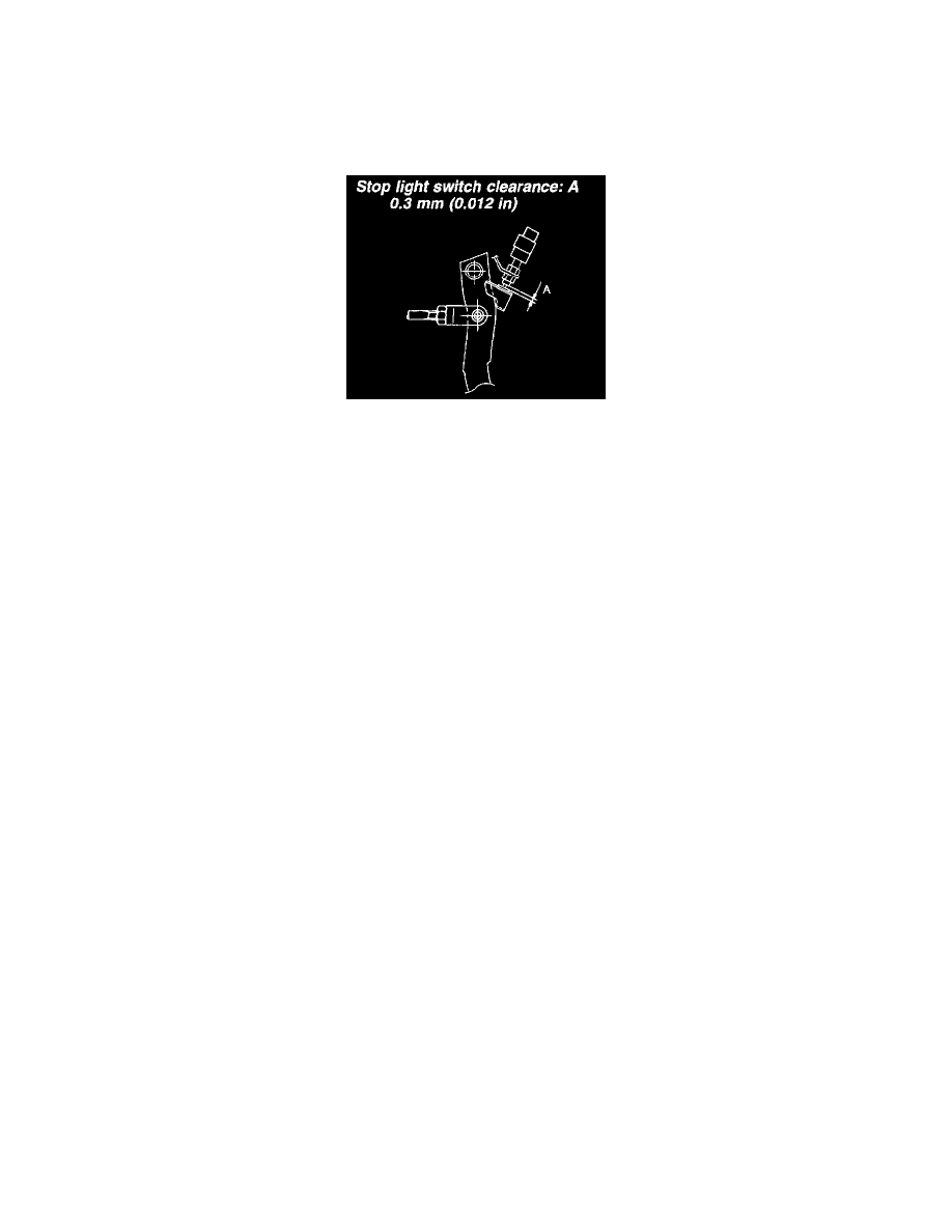
8) Measure the clearance between threaded end of stop light switch and stopper. If it is not within specified value, adjust it by adjusting the position
of stop light switch.
If it is not within specified value, adjust it by adjusting the position of stop light switch.
CAUTION: Be careful not to rotate the stop light switch.
Stop light switch clearance:
A 0.3 mm (0.012 inch)
9) Apply grease to operating rod connecting pin to prevent it from wearing.
10) Bleed air from the brake system.
Tightening torque (Air bleeder screw): 8 Nm (0.8 kgf-m, 5.8 ft. lbs.)
11) Conduct road tests to ensure brakes do not drag.