
Forester S F4-2.5L DOHC (1998)
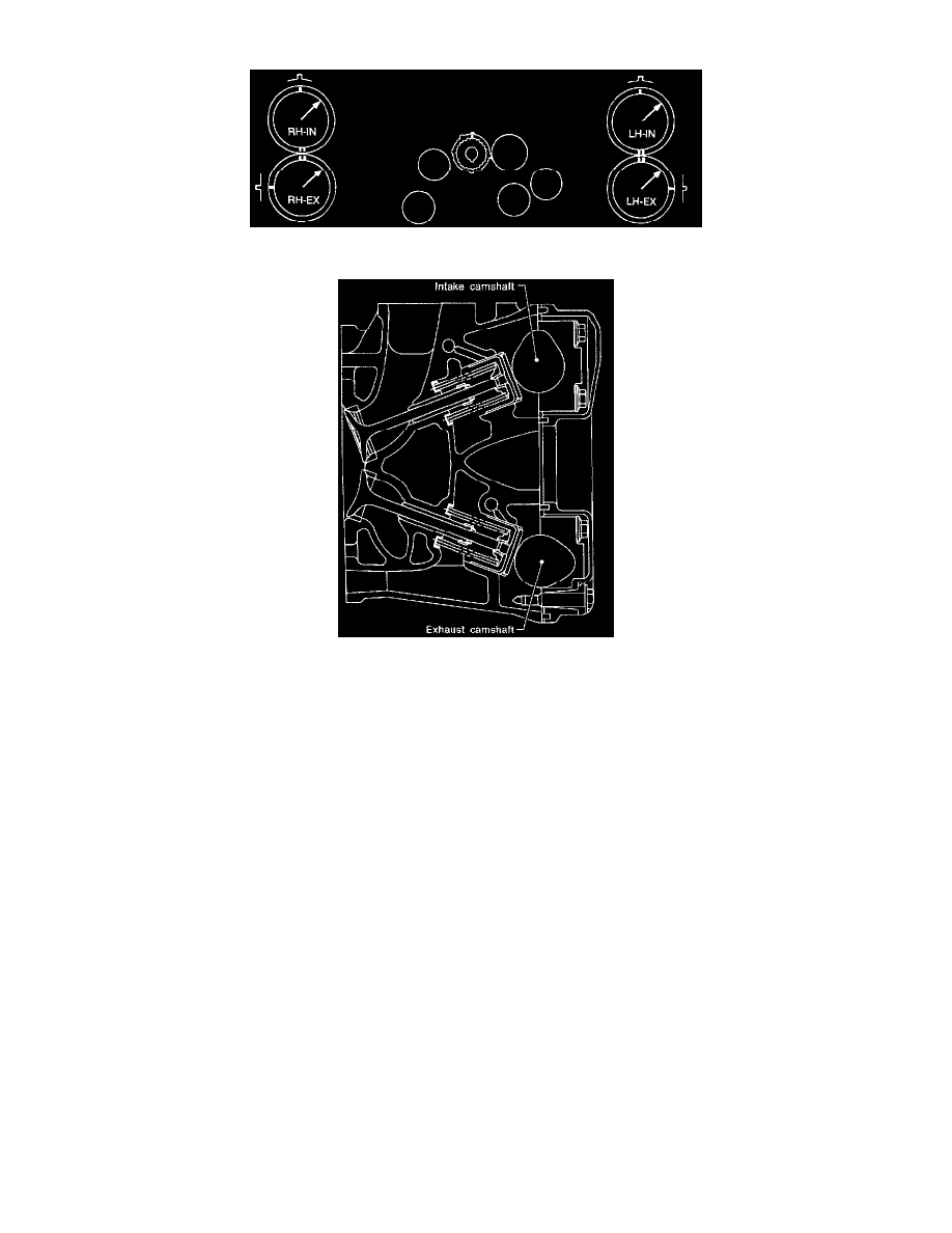
engine). Ensure double lines on intake and exhaust camshaft sprockets are aligned.
6) Ensure camshaft and crankshaft sprockets are positioned as shown.
CAUTION:
-
Intake and exhaust camshafts for this DOHC engine can be independently rotated with timing belts removed. As can be seen from the
figure, if intake and exhaust valves are lifted simultaneously, their heads will interfere with each other, resulting in bent valves.
-
When timing belts are not installed, four camshafts are held at the "zero-lift" position ' where all cams on camshafts do not push intake and
exhaust valves down. (Under this condition, all valves remain unlifted.)
-
When camshafts are rotated to install timing belts, #2 intake and #4 exhaust cam of left-hand camshafts are held to push their
corresponding valves down. (Under this condition, these valves are held lifted.) Right-side camshafts are held so that their cams do not
push valves down.
-
Left-hand camshafts must be rotated from the "zero-lift" position to the position where timing belt is to be installed at as small an angle as
possible, in order to prevent mutual interference of intake and exhaust valve heads.