
Hardtop 2WD F4-1595cc 1.6L (1983)
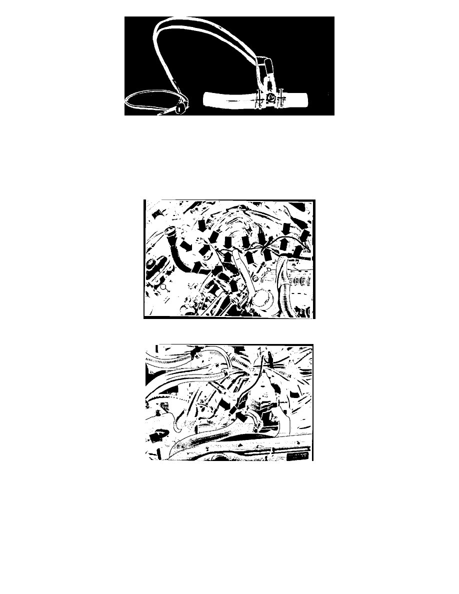
FIGURE 4 - HEATER HOSE ASSEMBLY
28.
Assemble the two short heater hoses onto the "T" fitting with two
(2)
hose clamps, and install the thermo-sensor from the thermostat housing with a new "O"-Ring, into the "T" fitting (See Figure 4).
29.
Connect the wiring harness to the thermo-sensor and secure the ground wire, using several washers as shims, to the "T" fitting with a 10 mm bolt.
30.
Saving the two original hose clamps, disconnect and discard the upper heater hose from between the A/T dipstick tube and the engine.
31.
With the two original hose clamps used on the heater hose, install the unit previously assembled in steps #28 and #29 with the longer hose toward
the firewall pointing down, being careful not to leave any kinks in the hose.
Figure 5A - Ground Eye Connector to Bolt
Figure 5B - Connect Male & Female Connectors
32.
Route the wire harness from the thermo-sensor toward the thermostat housing and ground the eye connector of the wiring harness to the 10 mm
bolt located at the rear of the intake manifold (See Figure 5A). Connect the male connector of the wire harness to the female connector originally
connected to the single pole thermo-sensor removed from the thermostat housing (See Figure 5B).