
Hatchback 4WD F4-1781cc 1.8L (1983)
3)
Carefully note the number (usually 3), of adjusting shims and remove from the compressor shaft. These may also be located in the recess of the
outer friction clutch hub. The same number of shims must be reinstalled on the compressor shaft before reinstallation of the outer friction clutch
hub. (See Figure 4).
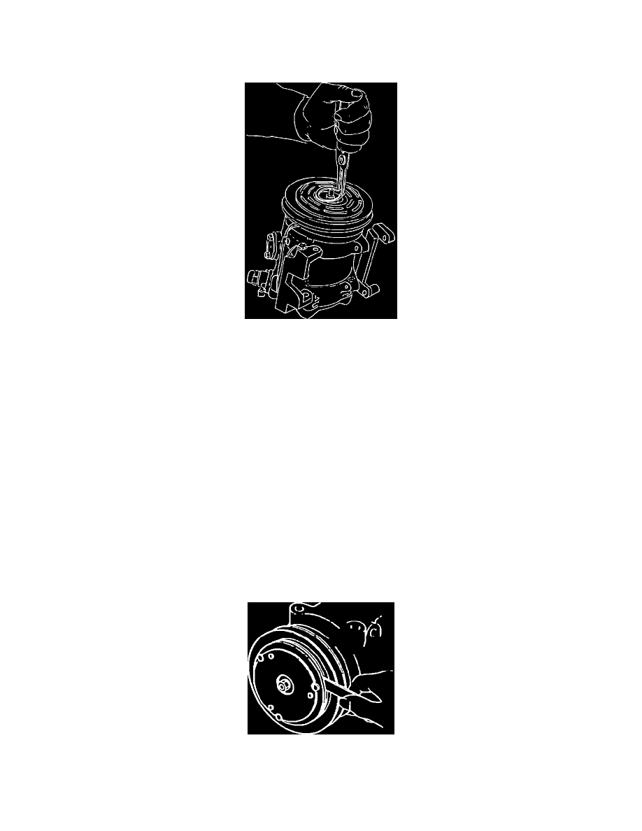
FIGURE 5 - Snap Ring Removal
4)
Remove the snap ring which retains the clutch hub pulley and bearing with a pair of external expanding snap ring pliers. (See Figure 5).
5)
Remove pulley and bearing assembly. If assembly cannot be removed by hand, tap it gently with a plastic hammer. If this does not remove the
assembly, use a commercially available puller such as a Kent Moore tool J-29884.
This completes the removal procedure for the pulley/bearing assembly. If the holding coil must be removed follow Step 6, otherwise go to Step 7
for reassembly procedures.
6)
Disconnect the power lead to the compressor. Remove the Phillips head screw which retains the holding coil wires. Remove large snap ring in
holding coil recess. NOTE: DO NOT REMOVE THE SMALLER SHAFT SEAL SNAP RING. The holding coil may now be easily replaced in
the reverse order of disassembly. Replace the snap ring with the flat side against the holding coil. Note the locating dowel on the holding coil and
fit into the corresponding hole in the compressor body when replacing assembly.
7)
Using a plastic mallet, tap the new pulley and bearing assembly onto the nose of the compressor until seated. Install the snap ring with the flat side
toward the pulley and bearing. Turn the pulley, making sure that there is no noise and that rotation is free.
8)
Before installing the clutch hub, it is important that both friction surfaces are completely clean with no oil or grease residue remaining. A non-oil
based solvent such as spray brake cleaner may be used to clean the surfaces. Fit the key into the key way on the compressor shaft if removed.
Install the same number of shim spacers that were removed onto the compressor shaft. Place the clutch hub on the shaft.
9)
Coat the shaft nut threads with non-hardening locktite (or equivalent) and torque to 15 ft.lbs. while holding the hub from turning with the clutch
spanner wrench.
FIGURE 6 - Hub to Pulley Clearance
10)
The hub to pulley clearance should be .020 - .031 inches. If the specified clearance is not attained, adjust the number of shims to achieve the
specified clearance. (See Figure 6)
NOTE:
WHEN REPLACING THE COMPRESSOR CLUTCH ASSEMBLY IT IS IMPORTANT TO BREAK IN THE FRICTION SURFACES