
Hatchback 4WD F4-1781cc 1.8L (1983)
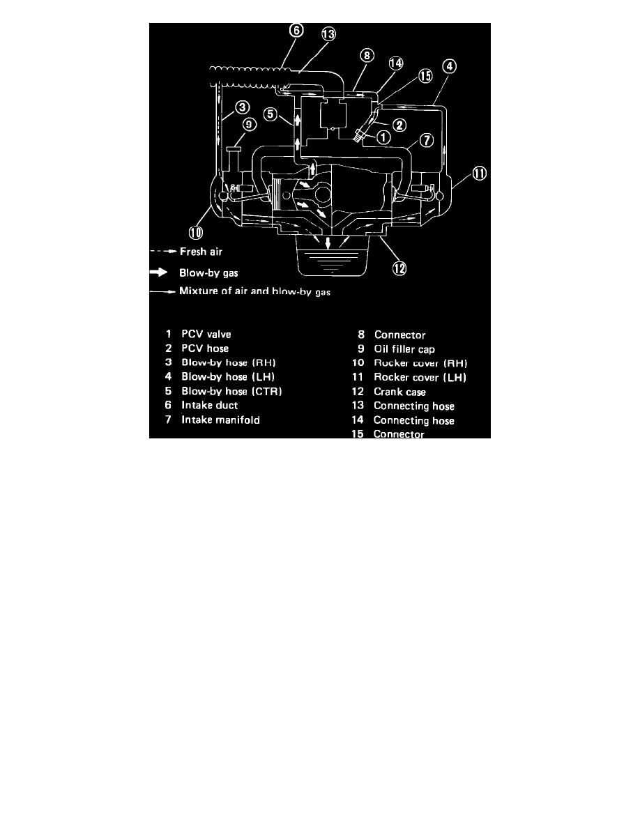
Fig.2 Positive crankcase ventilation system. Fuel injected models.
This system, FIGS. 1 and 2, prevents blow-by gases in the crankcase from escaping into the atmosphere. At part throttle operation, blow-by gases flow
from the crankcase through connecting hose on cylinders 2-4 rocker cover to the PCV valve and then into the intake manifold. Ambiant air is drawn
through the air cleaner and into the crankcase via connecting hose on cylinders 1-3 rocker cover. The ambiant air the mixes with the blow-by gases and
enters the intake system.
During wide open throttle operation, manifold vacuum is not sufficient to allow all of the gases to enter the intake manifold, so excess blow-by gases
enter
the air cleaner through the 1-3 rocker cover hose where it is drawn into the carburetor.
Under some driving conditons, oil from the crankcase will blow through connecting hose of 2-4 rocker cover and could be drawn into the intake
manifold. A connecting hose from the air cleaner to the 2-4 rocker cover hose prevents this by reducing vacuum.