
Hatchback 4WD F4-1781cc 1.8L (1983)
Alternator: Testing and Inspection
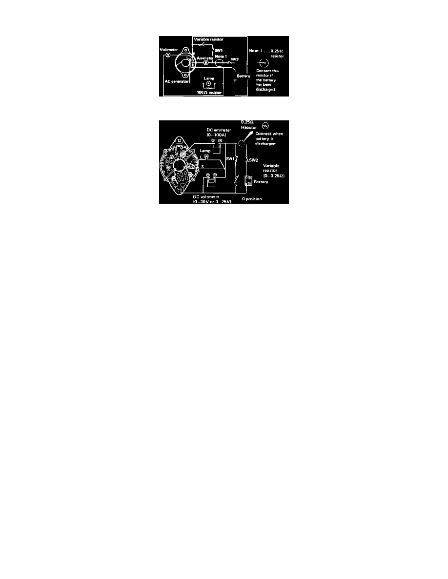
Fig.1 Circuit for testing alternator voltage & current output. Exc. XT Coupe
Fig.2 Circuit for testing alternator voltage & current output. XT Coupe
Mount alternator securely in a suitable test stand prior to testing. Ensure test stand battery is fully charged before conducting any alternator tests.
1.
Make the appropriate test connections shown in Figs. 1 and 2 to test alternator output speed.
2.
Open switch SW1 and close switch SW2, then operate alternator test stand.
3.
Slowly increase alternator speed while observing alternator output voltage.
4.
Output should be 13.5 volts at 1150 RPM on XT Coupe, or 13.5 volts at 900 RPM on all other models.
5.
Continue raising alternator speed while observing voltmeter. Voltage should remain within specified regulated range at 6000 RPM for XT Coupe
or 6000 RPM for all other models.
6.
Check current output with test connections as shown in Figs. 1 and 2. Close switches 1 and 2, then set variable resistor at minimum value.
7.
Increase alternator speed, using variable resistor to maintain voltage at 13.5 volts.
8.
Amperage should be within 10% of specified output at an alternator speed of 6000 RPM for XT Coupe or 5000 RPM for all other models.