
Impreza 2.5 RS Sedan AWD F4-2.5L SOHC (2002)
Discharge Air Temperature Sensor / Switch: All Technical Service Bulletins
A/C - Insufficient Cooling
NUMBER: 10-72-02R
DATE: 07/15/03
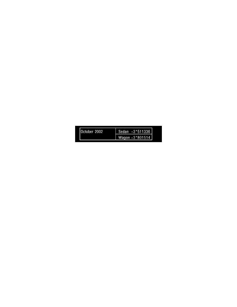
APPLICABILITY:
All 2002-2003MY Impreza Vehicles up to VIN 3*511336 & 3*801514
SUBJECT:
Countermeasure to Prevent Icing in the
Evaporator on Air Conditioned Vehicles
Correction
There is a possibility that icing could occur in the evaporator core of air conditioned equipped Impreza vehicles. During operation under warm, high
humidity conditions the customer would notice a diminished output of air from the dash vents causing the cabin temperature to rise. The icing condition
can be eliminated by replacing the original Thermosensor with a new fin sensitive type sensor and replacing it in the proper location.
The location of the original Thermosensor would depend on the production date of the vehicle. In December 2001, it was moved to the right side of the
evaporator. You will replace the surface mounted probe with the internal fin-mounted probe if the condition still exists on vehicles up to the production
change listed in this bulletin.
The part number for the new Thermosensor is P/N 72166FE010 & the Plastic Holder is P/N 73552FE000. The 0-rings needed are P/N 73039FA100 (1),
P/N 73039FA110 (1), P/N 73561FA040 (2), and P/N 73561FA030 (2); a total of 6 0-rings in all.
Production change took place with the Impreza vehicle information shown.
REPAIR PROCEDURE
1)
This procedure is different than what is shown in the service manual.
2)
Start by evacuating the A/C system.
3)
While the system is evacuating, start removing the (9) screws and 1 clip that hold the glove box assembly in place. Remove the connector for the
glove box light. This is a different type of clip. You must lift the end of the connector to get the locking tab out. There is no depression tab to push.
4)5GRemove the A pillar lower kick panel.
5)
Remove the daytime running lights relay and bracket as an assembly.
6)
Remove the daytime running light control module and bracket.
7)
Remove the heater control cable, intake side.
8)
Disconnect the heater recirculation door cable.
9)
Remove the two (2) nuts and one (1) bolt that hold the blower assembly in place. The upper nut is hidden behind the white wire tie clip that is
mounted to the same stud. At this time, disconnect the electrical connectors from the blower unit. Be careful of the sealing packing material on the
unit.
10)
Remove the five (5) screws and one (1) hidden black clip that hold the white evaporator cover to the main case.
a)
Lift the cover guide pin off then, and remove the cover. It is easier if you set the heater control to DEF before removing the cover.
11)
Check to insure the system is completely discharged.
12)
Remove the high and low pressure lines from the expansion valve block from under the hood on the firewall. There is one (1) 10 mm bolt holding
these two lines in place. If you are working on a WRX, it may be easier to also remove some of the firewall line clips to gain more clearance. If
there is not enough clearance, you may need to remove the air box or intercooler on turbo models.