
Impreza Coupe AWD F4-1820cc 1.8L SOHC (1995)
EGR Control Solenoid: Testing and Inspection
A faulty EGR control solenoid will set code 34 in the on-board diagnostic system.
WIRE COLOR CODE IDENTIFICATION
L:
Blue
B:
Black
Y:
Yellow
G:
Green
R:
Red
W: White
Br: Brown
Lg: Light green
Gr: Gray
Diagnostic Chart
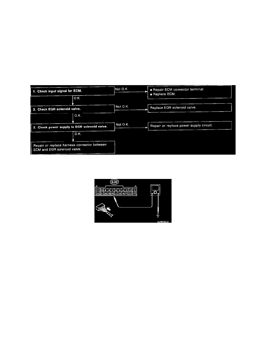
EGR CONTROL SOLENOID DIAGNOSTIC CHART
Input Signal
CHECK ECM VOLTAGE
With ignition "ON," measure voltage between ECM connector terminal (E30) 18 and ground. It should read 10 - 13 Volts.
CHECK EGR CONTROL SOLENOID
Disconnect EGR control solenoid connector and measure resistance between solenoid terminals. It should read 36 Ohms at 20°C (68°F).
CHECK POWER SUPPLY TO EGR CONTROL SOLENOID