
Impreza Coupe FWD F4-1820cc 1.8L SOHC (1995)
Control Module HVAC: Description and Operation
Compressor Control System
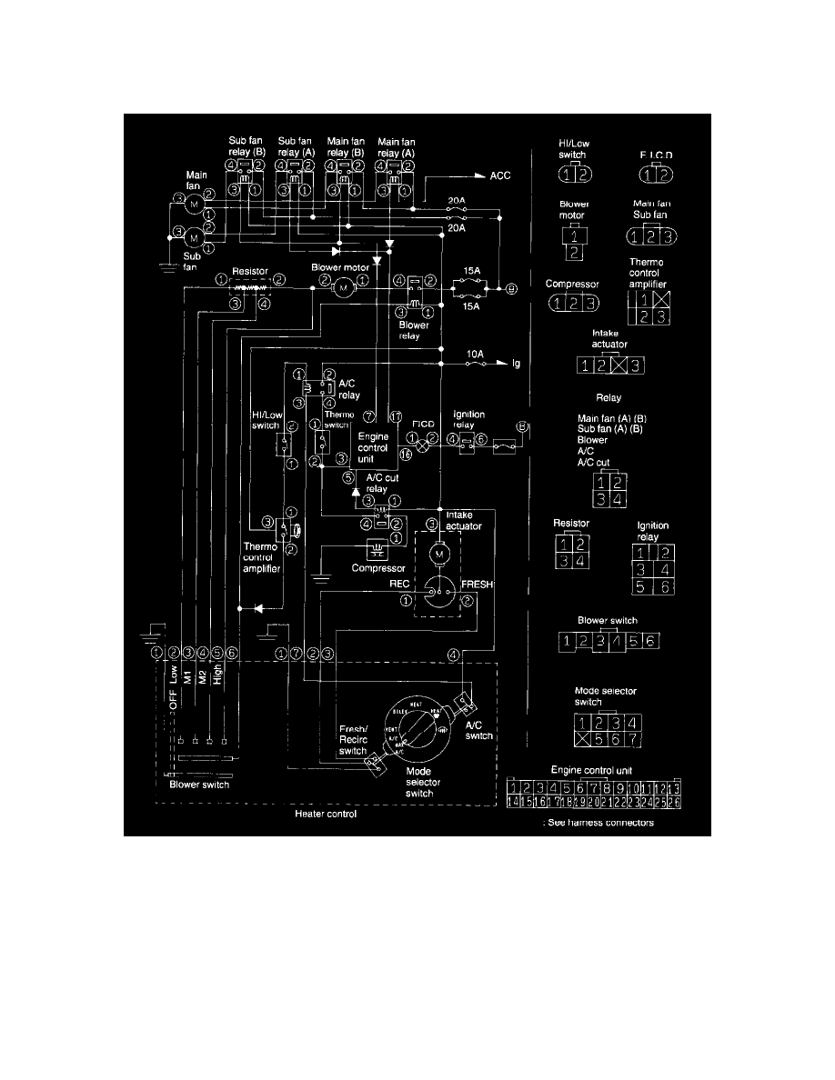
1. SCHEMATIC
Wiring Diagram
1. When the A/C switch and fan switch are turned ON, the A/C relay activates. The compressor and F.I.C.D. are turned on, and then the main and
sub fans also operate. Blower relay operates to direct the air flowrate determined by FAN switch position.
2. The thermo amplifier activates to stop the compressor clutch, F.I.C.D., and main and sub fans.
3. When the "High-Low" pressure switch operates, the compressor clutch and F.I.C.D. stop but the main and sub fans are operating.
4. When the fan control switch operates, both the main and sub fans operate