
Impreza Coupe FWD F4-1820cc 1.8L SOHC (1995)
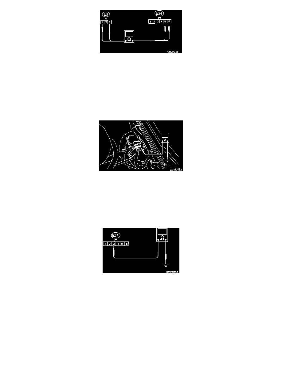
Harness Test
1.
Turn ignition OFF.
2.
Unplug connector from igniter.
3.
Measure resistance of harness connector between coil and igniter.
Connector & Terminal
Resistance
(E24) 5 - (E9) 1
10 Ohms maximum
(E24) 6 - (E9) 3
10 Ohms maximum
CHECK INPUT SIGNAL FOR IGNITER
Input Test
Check if voltage varies synchronously with engine speed when cranking, while monitoring voltage between igniter connector and body.
Connector & Terminal
Voltage
(E24) 1 - body
0.1 Volts minimum - 3.4 Volts maximum
(E24) 2 - body
0.1 Volts minimum - 3.4 Volts maximum
CHECK HARNESS CONNECTOR OF IGNITER GROUND CIRCUIT
Ground Test
1.
Turn ignition OFF.
2.
Measure resistance between igniter and body.
Connector & Terminal
Resistance
(E24) 3 - body
10 Ohms maximum
CHECK HARNESS CONNECTOR BETWEEN ECM AND IGNITER