
Impreza Coupe FWD F4-1820cc 1.8L SOHC (1995)
SHIFT CONTROL
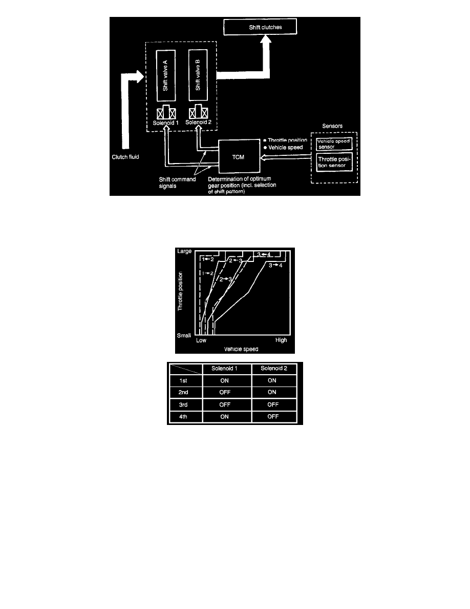
Gearshifting is controlled in response to driving conditions, according to the shift point characteristic data, as shown in the diagram, stored in the
Transmission Control Module (TCM). Solenoids are operated at the proper time corresponding to the shift pattern, throttle position, and vehicle
speed for smooth shifting.
When oil temperature is below approximately 10°C (50°F), the Vehicle can not be shifted to the 4th range.
1. Control module activates both solenoids 1 and 2 in response to throttle and vehicle speed signals.
2. Shift valve moves in response to solenoid operation, supplying/interrupting Clutch pressure to the line.
3. Gears are shifted by "ON"-"OFF" operation of both Solenoids as indicated in Table.
3-2 TIMING CONTROL
-
When shifting from 3rd to 2nd, the high clutch is disengaged. At the same time, oil pressure (which releases the brake band) is also released from
the servo piston 3rd release chamber (3R).
-
At this point, the servo piston moves to release oil pressure from the 3rd release chamber (3r) and apply oil pressure to the 2nd apply chamber.
This causes the brake band to be applied. In other words, high clutch "release" and brake band "application" are properly timed by electronic
control. This eliminates engine revving up under no load or hesitation.