
Impreza L Sport Wagon F4-2.2L SOHC (1999)
Front Cross-Member: Service and Repair
REMOVAL
1. Disconnect ground cable from battery.
2. Loosen front wheel nuts.
3. Jack-up vehicle, support it with safety stands (rigid racks), and remove front tires and wheels.
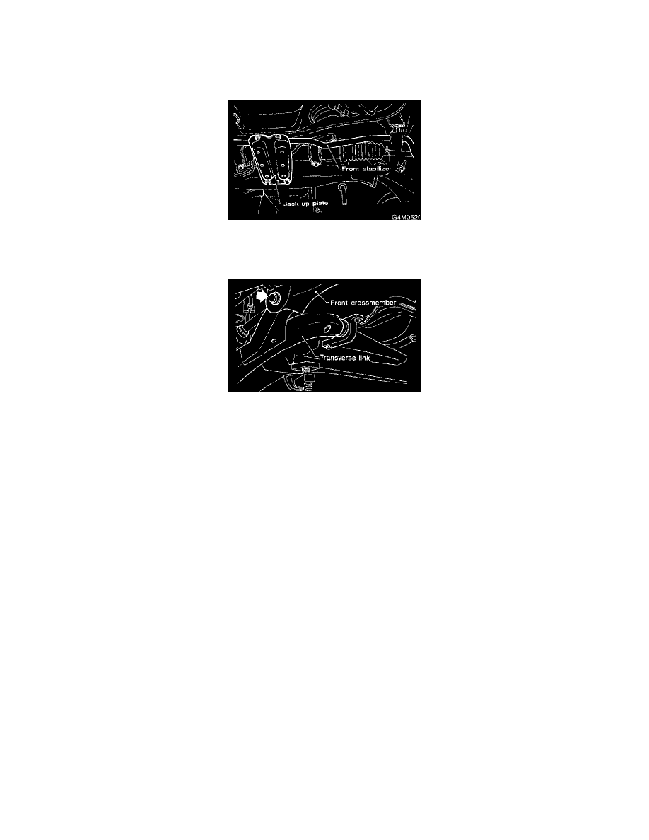
4. Remove both stabilizer and jack-up plate.
5. Disconnect tie-rod end from housing.
6. Remove front exhaust pipe.
7. Remove front transverse link from front crossmember.
8. Remove nuts attaching engine mount cushion rubber to crossmember.
9. Remove self-locking nuts connecting steering U/J and pinion shaft.
10. Lift engine by approximately 10 mm (0.39 inch) by using chain block.
11. Support crossmember with a jack, remove nuts securing crossmember to body and lower crossmember gradually along with steering gearbox.
CAUTION: When removing crossmember downward, be careful that tie-rod end does not interfere with Double Offset Joint (DOJ) boot.
INSTALLATION
1. Installation is in the reverse order of removal procedures.
CAUTION: Always tighten rubber bushing location when wheels are in full contact with the ground and vehicle is curb weight.
2. Tightening torque:
-
Transverse link bushing to crossmember: 98 ± 15 Nm (72 ± 11 ft. lbs.).
-
Stabilizer to bush: 25 ± 4 Nm (18.1 ± 2.9 ft. lbs.).
-
Tie-rod end to housing: 27.0 ± 2.5 Nm (19.9 ± 1.8 ft. lbs.).
-
Front cushion rubber to crossmember: 69 ± 15 Nm (51 ± 11 ft. lbs.).
-
Universal joint to pinion shaft: 24 ± 3 Nm (17.4 ± 2.2 ft. lbs.).
-
Crossmember to body: 98 ± 15 Nm (72 ± 11 ft. lbs.).
3. Purge air from power steering system.
NOTE: Check wheel alignment and adjust if necessary.