
Impreza L Sport Wagon F4-2.2L SOHC (1999)
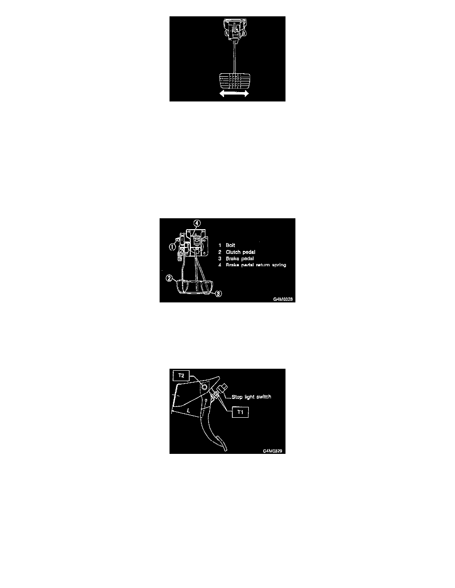
Move brake and clutch pedal pads in the lateral direction with a force of approximately 10 N (1 kg, 2 lb) to ensure pedal deflection is in specified
range.
Deflection of brake and clutch pedal:
Service limit 5.0 mm (0.197 in) or less
CAUTION: If excessive deflection is noted, replace bushings with new ones.
ASSEMBLY
Brake And Clutch Pedal
1) Attach stop light switch, etc. to pedal bracket temporarily.
2) Clean inside of bores of clutch pedal and brake pedal, apply grease, and set bushings into bores.
3) Align bores of pedal bracket, clutch pedal and brake pedal, attach brake pedal return spring and clutch pedal effort reducing spring (vehicle with
Hill holder), and then install pedal bolt.
Tightening torque: T2: 29 ± 7 Nm (3.0 ± 0.7 kg-m, 21.7 ± 5.1 ft. lbs.)
NOTE: Clean up inside of bushings and apply grease before installing spacer.
4) Set brake pedal position by adjusting position of stop light switch.
Pedal position: L 125.9 mm (4.96 inch)
Tightening torque: T1: 8 ± 2 Nm (0.8 ± 0.2 kg-m, 5.8 ± 1.4 ft. lbs.)
Accelerator Pedal
Clean and apply grease to spacer and inside bore of accelerator pedal. Install accelerator pedal onto pedal bracket.
INSTALLATION
1) Installation is in the reverse order of removal procedures.
CAUTION: