
Impreza Outback Sport AWD F4-2.5L SOHC (2002)
3. Remove the two bolts which hold washer tank, then secure the tank away from working area.
4. Disconnect the spark plug cords from spark plugs (LH Side)
5. Disconnect the PCV hose from rocker cover (LH).
6. Remove the bolts, then remove the rocker cover (LH).
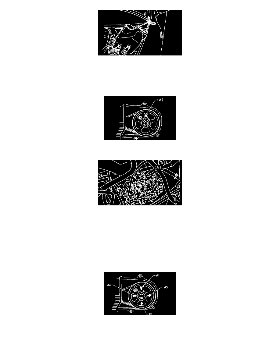
9. Set #1 cylinder piston to top dead center of compression stroke by rotating the crankshaft pulley clockwise using ST.
ST 499977100 CRANKSHAFT PULLEY WRENCH
NOTE: When the arrow mark (A) on camshaft sprocket (LH) comes exactly to the top, #1 cylinder piston is brought to the top dead center of
compression stroke.
10. Measure #1 cylinder valve clearance by using thickness gauge (A).
CAUTION:
^
Insert the thickness gauge in as horizontal a direction as possible with respect to the valve stem end face.
^
Measure the exhaust valve clearances while lifting-up the vehicle.
Valve clearance:
Intake: 0.20 ±0.02 mm (0.0079 ±0.0008 inch)
Exhaust: 0.25 ±0.02 mm (0.0098 ±0.0008 inch)
11. If necessary, adjust the valve clearance.
12. Similar to measurement procedures used for #1 cylinder, measure #2, #3 and #4 cylinder valve clearances.
NOTE:
^
Be sure to set the cylinder pistons to their respective top dead centers on compression stroke before measuring valve clearances.
^
To set #3, #2 and #4 cylinder pistons to their top dead centers on compression stroke, turn the crankshaft pulley clockwise 90° at a time
starting with arrow mark on left-hand camshaft sprocket facing up.