
Impreza RS Coupe AWD F4-2.5L SOHC (1999)
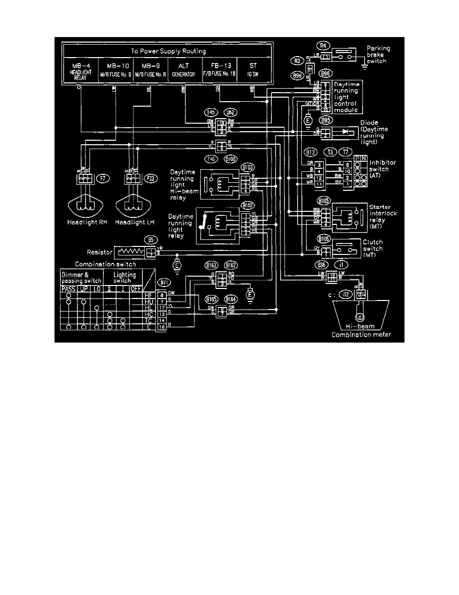
Dimmer Switch: Electrical Diagrams
With Daytime Running Lamps (DRL)
Fuse/Relay Locations: For fuse and/or relay locations refer to Starting and Charging / Power and ground Distribution: See: Power and Ground
Distribution
Ground Locations: For ground locations refer to Vehicle / Locations / Grounds: See: Locations/Ground Locations
Connector Locations: For connector locations refer to Vehicle / Locations / Connectors: See: Locations/Connector Locations
Component Locations: For component locations refer to Vehicle / Locations / Harness: See: Locations/Harness Locations
NOTE:
To locate Connectors, Components and/or Grounds using Harness Connector Location diagram(s) use the connector's alphanumeric name [referred to in
the wiring diagram(s)] to identify the apropriate Harness Connector Location diagram. For example, the prefix letter "B" in the connector name "B-38"
indicates the location is displayed in the Bulkhead Wiring Harness Connector Location diagram.
Legend:
Prefix ................................................................................................................................................................................ Harness Connector Diagram
F ................................................................................................................................................................................................................................. Front
B .......................................................................................................................................................................................................................... Bulkhead
i ............................................................................................................................................................................................................... Instrument Panel
P ................................................................................................................................................................................................................ Power Window
D ................................................................................................................................................................................................................................ Door